Ever stared at a tangled web of network devices, cables, and subnets and thought, “How does any of this actually work?” Managing a network without a clear visual plan can be frustrating, time-consuming, and prone to costly errors. That’s why a logical network diagram is a game-changer. In this guide, we’ll cover what a logical network diagram is, how it differs from a physical network diagram, why it’s useful, and how to create one, including ready-to-use templates and best practices to streamline your workflow.
What Is a Logical Network?
A logical network is like a blueprint for your network, but instead of showing the cables and hardware, it focuses on how data flows and how devices communicate. Think of it as a “map of interactions” that illustrates connections, IP addresses, subnets, and traffic flow, without getting bogged down in the physical details of routers, switches, or server racks.
In contrast, a physical network diagram shows the actual hardware layout, including devices, cables, ports, and physical locations. If you’ve ever wondered why IT teams sometimes talk about logical vs physical network diagrams, this is the difference: one is about function and connectivity (logical), and the other is about hardware placement and setup (physical). You might also see this phrased as physical network diagram vs logical or logical network diagram vs physical network diagram, all pointing to the same distinction.
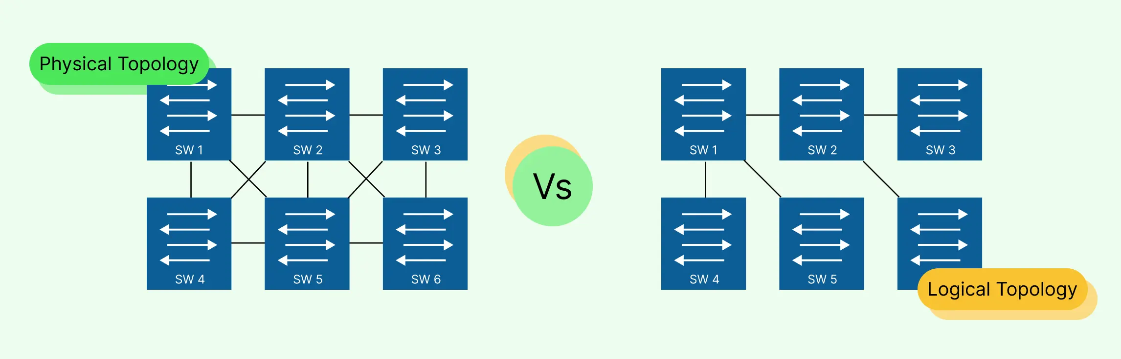
Logical Network Diagram vs Physical Network Diagram
When planning, managing, or troubleshooting networks, it’s important to understand the difference between a logical network diagram and a physical network diagram. While they’re related, they serve very different purposes. Here’s a quick, easy-to-digest comparison:
| Feature | Logical Network Diagram | Physical Network Diagram |
| Focus | Shows how data flows and how devices communicate | Shows hardware layout including devices, cables, and ports |
| Components Displayed | Subnets, IP addresses, routing paths, firewalls, VLANs | Servers, switches, routers, cabling, racks, physical locations |
| Purpose | Plan, optimize, and troubleshoot network connectivity | Understand the physical setup, manage hardware, and install or maintain devices |
| Level of Detail | Conceptual; emphasizes network logic and relationships | Concrete; emphasizes physical connections and placements |
| Use Cases | Network design, traffic flow visualization, security mapping | Hardware deployment, wiring management, maintenance, inventory |
| Flexibility | Easier to update as networks evolve | Harder to change; reflects actual physical infrastructure |
| Examples | Visualizing subnet communication, cloud network flow, firewall rules | Mapping office LAN wiring, switch-to-router connections, server room layout |
💡 Pro tip: Teams often create both diagrams together. The logical diagram guides decision-making and problem-solving, while the physical diagram ensures the actual implementation matches the plan. Using Creately makes it simple to switch between the two views and keep both diagrams up to date without extra hassle.
Why Use a Logical Network Diagram?
If you’ve ever stared at a messy network map or scrambled through confusing spreadsheets just to figure out who’s connected to what, you know the frustration of scattered workflows and unclear network layouts. That’s exactly where a logical network diagram comes to the rescue.
A logical network diagram focuses on how data moves through your network, helping teams see the big picture and make smart decisions fast. But what is a logical network diagram useful for? Let’s break it down:
Key Benefits of a Logical Network Diagram
- Clarity: Visualize connections between devices, subnets, and servers at a glance. No more guessing who’s talking to what.
- Speed: Plan upgrades, troubleshoot issues, or onboard new staff without hours of confusion.
- Troubleshooting: Identify potential bottlenecks, misconfigurations, or points of failure before they cause downtime.
- Planning: Map out future network expansions, cloud migrations, or security upgrades logically, so changes won’t break existing workflows.
- Team Collaboration: Share a single source of truth across IT, engineering, and management teams, everyone’s on the same page.
Real-World Uses of Logical Network Diagrams
- Onboarding new IT staff: Instead of handing over a stack of manuals, give them a visual map of the network. They’ll understand roles, connections, and priorities in minutes.
- Planning network upgrades: Spot traffic bottlenecks and optimize routing without touching a single cable.
- Optimizing traffic flow: See which devices or subnets handle the most traffic and make smarter decisions for load balancing or segmentation.
With a logical network diagram, what used to feel chaotic suddenly becomes organized, predictable, and easy to act on. And using a tool like Creately means you can create, update, and share diagrams instantly, making team collaboration smoother than ever.
How to Make a Logical Network Diagram
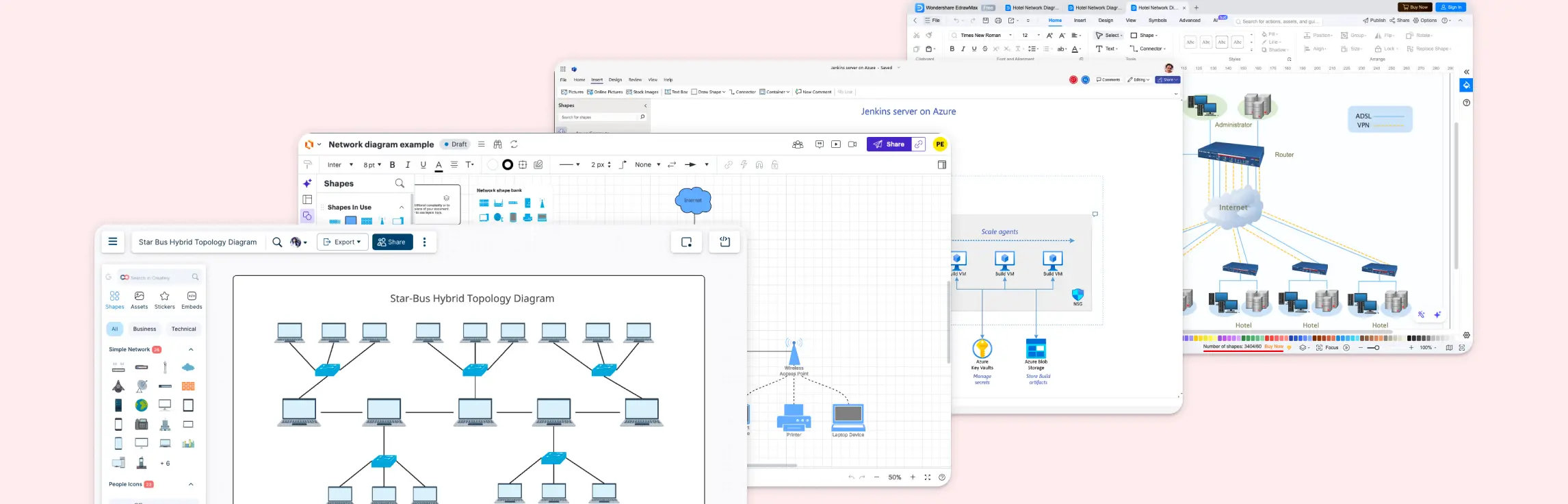
Creating a logical network diagram doesn’t have to be complicated or frustrating. With the right approach and tools like Creately, you can map out your network clearly and quickly. Here’s a simple step-by-step guide:
Step 1: Identify Network Components
Start by listing all the key devices and elements in your network: servers, routers, switches, firewalls, workstations, and cloud services. Knowing exactly what you need to map ensures your diagram will be accurate and useful.
Step 2: Determine Connections and Flow
Next, figure out how your devices communicate. Which servers talk to which workstations? How does traffic flow between subnets? This step is all about understanding data paths, dependencies, and relationships. Your diagram should reflect the network’s logical structure, not just physical placement.
Step 3: Choose a Visualization Style
Decide how you want to represent your network visually. Use symbols, colors, and layers to make complex information easier to digest. For example, color-code subnets, use unique icons for different device types, and layer cloud resources separately from on-premise servers. A clear visual style makes your diagram instantly readable.
Step 4: Build the Diagram in Creately
Now comes the easy part: creating your diagram in Creately. The platform makes it simple:
- Drag-and-drop shapes: Quickly place servers, routers, switches, and other devices onto your canvas.
- Smart connectors: Automatically link devices while keeping lines organized and readable.
- Templates: Start from pre-built logical network diagram templates to save time and reduce errors.
- Cloud collaboration: Share your diagram with your team, get real-time feedback, and collaborate seamlessly, even across remote locations.
The result? A logical network diagram that’s accurate, easy to understand, and ready to guide decisions, all without the frustration of messy sketches or confusing spreadsheets. With Creately, building, updating, and sharing diagrams becomes fast, intuitive, and surprisingly easy.
Logical Network Diagram Examples
Creating a logical network diagram from scratch can sometimes feel overwhelming, especially when you’re juggling multiple devices, subnets, and traffic flows. That’s where ready-to-use templates come in handy. Templates give you a head start, reduce mistakes, and help you visualize complex networks quickly.
With Creately, you can access templates for a wide range of network setups, from simple office networks to advanced enterprise environments. Here are some examples to get you started:
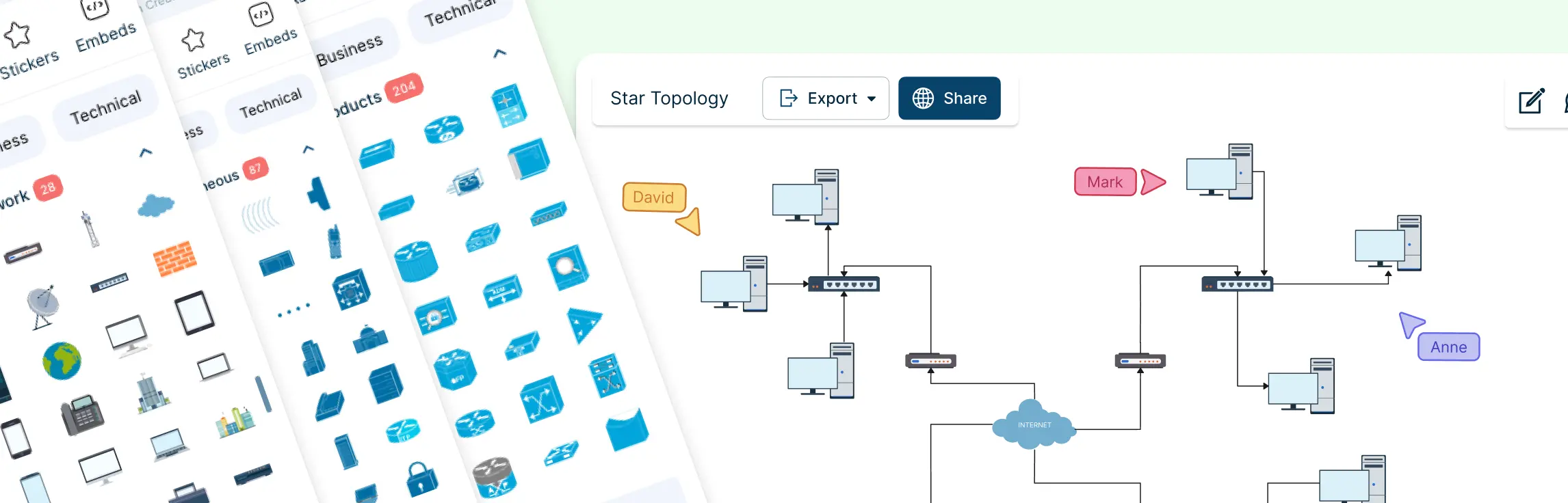
1. Simple Network Diagram Example
This template provides a clean, beginner-friendly view of a small network, showing essential devices like computers, routers, and switches with clear connections. It’s perfect for quickly understanding the flow of data in a basic setup and is ideal for small offices or home networks.


2. Advanced Home Network With Cisco
Designed for tech enthusiasts or home labs, this template highlights advanced configurations using Cisco devices. It includes routers, switches, firewalls, and Wi-Fi segments, helping users visualize a more complex network without getting lost in details.

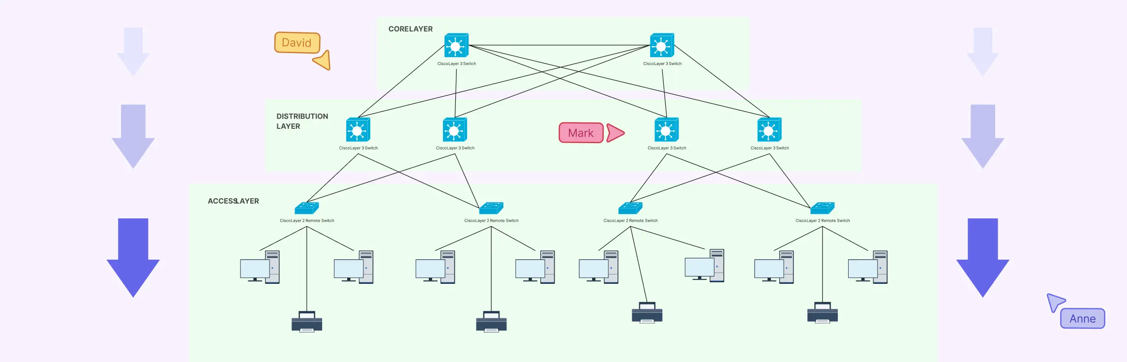
3. LAN HLD – Network Diagram
The LAN High-Level Design (HLD) template is aimed at office and enterprise environments, providing a conceptual overview of your local area network. It shows subnets, servers, switches, and user endpoints in a clear, structured layout for planning and presentations.

4. Network with Multiple VLANs and a DHCP Server
Perfect for enterprise-level network planning, this template illustrates multiple VLANs, a DHCP server, and segmented traffic flows. It helps teams manage large-scale networks efficiently and ensures proper communication between different departments or segments.

5. Zone Segmentation in an Office Network (Local Network Security)
This template focuses on network security by visualizing segmented zones within an office environment. It clearly shows firewalls, access points, and restricted areas, helping IT teams enforce security policies while maintaining seamless connectivity.

More Network Diagram Templates
Why Use Templates?
- Save Time: No need to start from a blank canvas, just customize an existing layout.
- Reduce Errors: Templates are pre-structured with logical connections and best practices.
- Collaborate Easily: Share your diagram instantly with your team and update in real-time.
🚀Pro Tip: Pick a template closest to your network type and tweak it for your environment. With Creately, updating diagrams is fast and intuitive, whether you’re adding new devices, changing IPs, or redesigning your network layout.
Best Practices for Logical Network Diagrams
Creating a logical network diagram is more than just dropping shapes on a canvas, it’s about clarity, accuracy, and usability. Following a few best practices ensures your diagram is not only visually appealing but also truly useful for your team.
Tips for Clarity:
- Label everything clearly: Devices, subnets, VLANs, and IP addresses should all be easy to read.
- Group related elements: Keep servers, switches, or departmental networks together to make the diagram intuitive.
- Use color coding: Assign colors to subnets, security zones, or traffic flows to make patterns and dependencies instantly recognizable.
- Plan for scalability: Design your diagram so it can grow as your network expands, without turning chaotic.
Common Mistakes to Avoid:
- Overcomplicating diagrams: Too many lines or devices can overwhelm viewers. Focus on the logical flow rather than every single physical connection.
- Missing nodes or connections: Even small omissions can create confusion during planning or troubleshooting.
- Mixing logical and physical details: Keep your logical diagram focused on data flow and relationships, not cabling or hardware placement.
A logical network diagram transforms the chaos of scattered workflows and complex network setups into a clear, actionable visual map. From understanding data flow to planning upgrades, troubleshooting issues, and collaborating across teams, it’s a vital tool for any IT environment. By following best practices, leveraging templates, and using a tool like Creately, you can create diagrams that are not only accurate but also easy to update and share. Ready to take control of your network? Explore Creately today and start visualizing your network like a pro, clear, simple, and fast.
Helpful Resources
Learn how to draw a network diagram step by step, from planning what to include to laying out components clearly and choosing the right symbols.
Discover key bus topology diagram elements, highlight common design patterns, and point out the limitations you need to account for when working with this topology.
Understand how to approach Cisco network topology diagrams with confidence and create visuals that are practical, accurate, and easy to understand.
Learn how to create a home network setup diagram step by step, understand common layouts, follow practical best practices, and use free templates to map your setup.
Discover how to create a wide area network diagram step by step, understand key components, WAN examples, and follow proven best practices.
Explore what hybrid topology diagrams are, the hybrid types & examples, highlight advantages and disadvantages, provide a step-by-step creation process, and best practices.
Everything you need to know about LANs, from the basics and key components to network types, advantages, and best practices.