Managing a network that spans multiple departments, locations, or devices can feel like juggling puzzle pieces in the dark. That’s where a hybrid topology diagram comes in. By visually mapping how different network topologies connect and work together, you can turn chaos into clarity. This guide will walk you through what hybrid topology diagrams are, explore the types and examples, highlight advantages and disadvantages, provide a step-by-step creation process, and share best practices to make your diagrams clear, scalable, and actionable.
What Is a Hybrid Topology?
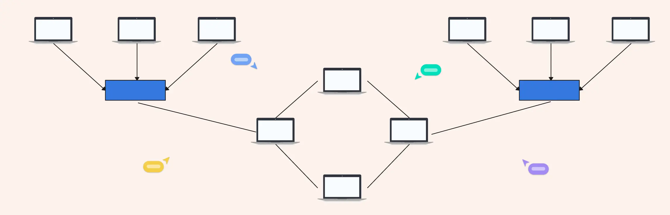
A hybrid topology is a visual representation of a network that combines two or more network topologies into a single, connected layout. Instead of explaining complex connections through long documentation or scattered notes, the diagram shows how different topologies, such as star, bus, ring, or hierarchical, work together within one network.
In short, a hybrid topology diagram turns complexity into clarity. It gives you a clear, at-a-glance view of how your entire network is structured and how each part connects to the rest.
Why Hybrid Topology Diagrams Are Essential
Modern networks evolve fast. Without a visual reference, things can quickly become confusing. This is where a well-designed hybrid topology diagram becomes indispensable.
- For network planning Diagrams help teams design smarter networks from the start. By mapping out different topology combinations visually, teams can identify bottlenecks early, plan efficient data flow, and choose the right structure for each part of the network.
- For troubleshooting When something breaks, guessing wastes time. A hybrid topology diagram makes it easier to pinpoint where issues might be occurring, whether it’s a failed node, a broken connection, or a topology-specific limitation, so teams can resolve problems faster.
- For scaling and future growth As organizations grow, networks need to expand without chaos. Hybrid topology diagrams help teams visualize how new devices, departments, or locations can be added without disrupting existing systems.
- For team alignment and communication Not everyone on the team speaks “network jargon.” Diagrams create a shared visual language that aligns IT teams, stakeholders, and decision-makers, reducing miscommunication and speeding up collaboration.
Who Uses Hybrid Topology Diagrams?
Hybrid topology diagrams are widely used across technical and educational environments, including:
- IT teams managing complex organizational networks
- Network engineers designing, optimizing, and maintaining infrastructure
- Educators teaching networking concepts visually
- Students learning how real-world hybrid networks are structured
Whether you’re designing an enterprise network or learning the fundamentals, a hybrid topology diagram makes understanding and managing complex networks far more intuitive.
Types of Hybrid Topologies
Hybrid networks aren’t one-size-fits-all. Different combinations of topologies solve different problems, which is why understanding the types of hybrid topologies is key when designing or reading a hybrid topology diagram. Below are the most common and practical hybrid topology structures you’ll encounter in real-world networks.
1. Star–Ring Hybrid Topology
A star–ring hybrid topology combines the centralized control of a star topology with the continuous loop of a ring topology.


How the star and ring structures work together
In this setup, multiple star networks are connected through a ring backbone. Each star has a central hub or switch, and these hubs are linked together in a circular (ring) structure. This allows data to flow around the ring while still maintaining the simplicity of star-based connections at the local level.
Typical use cases
- Corporate departments connected through a central backbone
- Campus networks with multiple buildings
- Systems that need structured communication with controlled access
Strengths and limitations
Strengths:
- Easier fault isolation within individual star segments
- Predictable data flow across the ring
- Balanced performance and control
Limitations:
- Ring failure can impact multiple star networks
- More complex setup than single-topology designs
Star-Ring Hybrid Network Components
In a star-ring hybrid topology diagram, you’ll typically see:
- Multiple star clusters
- Central hubs connected in a circular loop
- Clear separation between local nodes and backbone connections
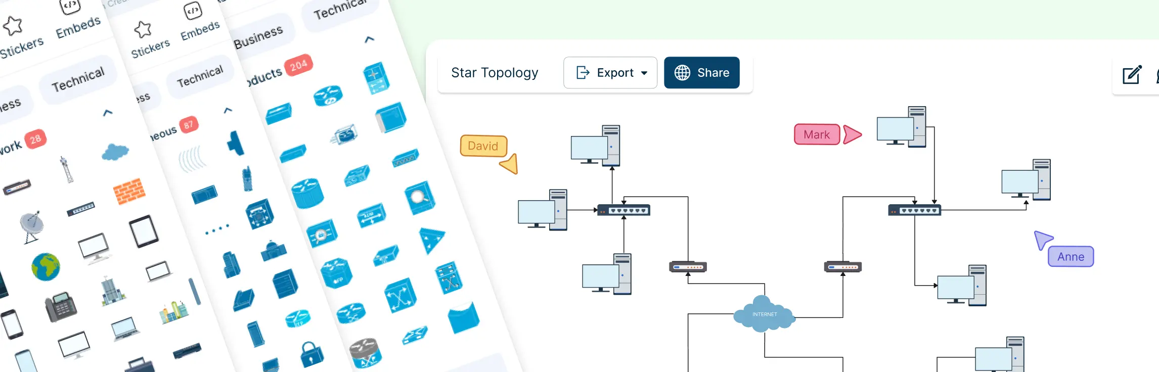
2. Star–Bus Hybrid Topology
The star–bus hybrid topology is one of the most widely used hybrid network designs due to its simplicity and scalability.

How star nodes connect via a bus backbone
Here, several star networks connect to a single linear bus backbone. Each star functions independently, while the bus acts as the main communication channel between them.
Common enterprise and campus network scenarios
- Office floors connected through a shared backbone
- Educational campuses with multiple labs or departments
- Small-to-medium enterprise networks
Why is this hybrid popular?
This hybrid topology is popular because it’s:
- Cost-effective compared to mesh-heavy designs
- Easy to expand by adding new star segments
- Simple to visualize and maintain
Star-Bus Hybrid Network Components
A clear hybrid topology diagram for this setup usually includes:
- A central bus line
- Multiple star hubs branching off
- End devices connected to each hub
- Labels for backbone and access points
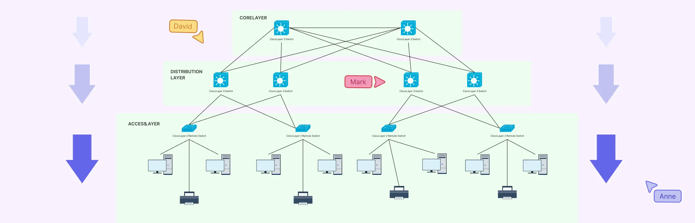
3. Hierarchical (Tree-Based) Hybrid Network Topology
A hierarchical hybrid topology, often called a tree-based topology, is a structured hybrid model designed for large and complex networks.

How hierarchical topology fits under hybrid models
This topology blends star networks into multiple levels, creating a tree-like structure. Each level may follow a star configuration, but together they form a hybrid system that supports controlled data flow and scalability.
Components of Hierarchical (Tree-Based) Hybrid Network Topology
A hierarchical hybrid network is organized into distinct layers that make the network scalable, manageable, and easy to visualize in a hybrid topology diagram. The main components include:
1. Core Layer
- Acts as the high-speed backbone of the network
- Connects major network segments and handles heavy traffic
- Ensures reliability and redundancy for critical data flow
2. Distribution Layer
- Serves as the intermediary between the core and access layers
- Routes traffic, applies security policies, and aggregates connections from the access layer
- Controls data flow efficiently across multiple segments
3. Access Layer
- The entry point for end devices like computers, printers, and IoT devices
- Handles local traffic and provides network access to users
- Branches out in the hybrid topology diagram to show device-level connections clearly
Best for large, multi-level organizations
Hierarchical hybrid topology is ideal for:
- Large enterprises
- Universities and school districts
- Data centers and distributed organizations
In a hybrid topology diagram, this structure clearly shows authority, flow direction, and network segmentation, making it easier to manage, troubleshoot, and scale over time.
Hybrid Topology Advantages and Disadvantages
Understanding both the strengths and limitations of hybrid topology is crucial when deciding if it’s the right network design for your organization. A clear hybrid topology diagram can help visualize these trade-offs, making planning and management easier.
Advantages of Hybrid Topology
1. Scalability
Hybrid networks are highly scalable. You can expand one part of the network, like adding a new star segment, without disrupting the rest. This makes it ideal for growing organizations that need a flexible design.
2. Flexibility
By combining multiple topologies, hybrid networks adapt to different departmental or functional needs. For example, a star topology can serve one department while a ring handles another, all within the same hybrid network.
3. Fault Isolation
Problems in one segment don’t necessarily affect the entire network. A well-structured hybrid topology allows teams to identify and isolate faults quickly, reducing downtime.
4. Performance Optimization
Hybrid networks can optimize performance by assigning appropriate topologies to different parts of the network. High-traffic areas can use faster structures like star, while redundancy can be handled with ring configurations.
5. Adaptability to Business Growth
As organizations evolve, hybrid topology networks can incorporate new technologies, locations, or devices seamlessly, ensuring the network grows with the business without major redesigns.
Disadvantages of Hybrid Topology
1. Design Complexity
Because hybrid networks combine multiple topologies, the design process can be complicated. Planning connections, ensuring compatibility, and maintaining efficiency requires careful attention.
2. Higher Initial Setup Cost
Implementing a hybrid network can be more expensive than a single-topology network. More equipment, cabling, and configuration work may be needed upfront.
3. Requires Clear Documentation and Diagrams
Without a clear hybrid topology diagram, managing or troubleshooting the network becomes difficult. Detailed documentation and visual representations are essential to keep the network organized and maintainable.
How to Create a Hybrid Topology Diagram (Step-by-Step)
Designing a hybrid network might sound complex, but breaking it down into clear steps makes it manageable, and a hybrid topology diagram brings it all to life visually. Here’s a practical, step-by-step approach that IT teams, network engineers, and students can follow.
Step 1: Identify Network Requirements
Before you start drawing, understand what the network needs to achieve:
- How many devices and users will connect?
- What are the performance and redundancy requirements?
- Are there specific departmental or location constraints?
Documenting these requirements upfront ensures your hybrid topology diagram is accurate and aligned with real-world needs.
Step 2: Choose Topology Combinations
Next, decide which topologies to combine for different parts of the network:
- Star for centralized, high-traffic segments
- Bus for simple linear connections
- Ring for redundancy in critical paths
- Hierarchical for multi-level, large networks
Selecting the right combination for each segment ensures the network is efficient, scalable, and reliable.
Step 3: Define Nodes, Connections, and Hierarchy
Now map out the network visually:
- Identify nodes (routers, switches, servers, end devices)
- Define connections between nodes based on chosen topologies
- Establish hierarchy if using a tree-based or multi-level design
Creating a hybrid topology diagram at this stage helps teams see the big picture, detect potential bottlenecks, and plan for fault isolation.
Step 4: Validate Performance and Scalability
Finally, test your design against expected network loads:
- Can the network handle peak traffic?
- Are critical segments redundant for fault tolerance?
- Can new devices or segments be added without disruption?
A network diagram template is invaluable here, which allows you to simulate changes visually and make adjustments before physical deployment, saving time, money, and frustration.
This structured approach ensures your hybrid network is planned, efficient, and easy to maintain, and it sets the stage for leveraging tools like Creately to bring your design to life with ready-made templates and collaborative features.
Best Practices for Designing an Effective Hybrid Topology Diagram
Creating a hybrid topology diagram isn’t just about connecting nodes, it’s about making the network understandable, maintainable, and future-proof. Following these best practices ensures your diagrams are both visually clear and technically accurate.
1. Keep Layouts Clean and Readable
A cluttered diagram defeats the purpose of visual clarity. Arrange nodes logically, minimize crossing lines, and group related devices or segments together. This makes it easy for anyone, engineer or stakeholder, to understand the network at a glance.
2. Use Consistent Symbols and Labeling
Standardized icons for routers, switches, servers, and end devices make the diagram intuitive. Consistent labeling of nodes and connections helps teams identify parts of the network quickly and reduces miscommunication.
3. Plan for Scalability
Hybrid networks often grow over time. When designing your diagram, leave space for future nodes and segments. Visualize how new devices or topologies can be integrated without disrupting the existing layout.
4. Document Assumptions Clearly
Include notes about network protocols, bandwidth expectations, redundancy plans, and any assumptions made during design. This documentation ensures that anyone referencing the diagram understands the rationale behind design decisions.
5. Review Diagrams Collaboratively
Hybrid topology diagrams are more effective when reviewed by multiple stakeholders. Collaborate with IT teams, network engineers, and even non-technical managers to ensure the diagram accurately represents the network, meets business needs, and is easy to understand.
Following these best practices transforms a hybrid topology diagram from a simple visual into a powerful communication and planning tool, helping teams stay aligned, reduce errors, and plan for growth efficiently.
A hybrid topology diagram is more than just a visual; it’s a roadmap for designing, managing, and scaling complex networks with confidence. From understanding the different hybrid structures to weighing their advantages and disadvantages, and following a clear, step-by-step creation process, you now have the tools to plan networks that are efficient, reliable, and easy to communicate. Ready to turn your network complexity into clarity? Try Creately’s hybrid topology diagram templates and start visualizing your network like a pro—fast, intuitive, and collaborative.
Helpful Resources
Learn how to draw a network diagram step by step, from planning what to include to laying out components clearly and choosing the right symbols.
Discover key bus topology diagram elements, highlight common design patterns, and point out the limitations you need to account for when working with this topology.
Understand how to approach Cisco network topology diagrams with confidence and create visuals that are practical, accurate, and easy to understand.
Learn how to create a home network setup diagram step by step, understand common layouts, follow practical best practices, and use free templates to map your setup.
Discover how to create a wide area network diagram step by step, understand key components, WAN examples, and follow proven best practices.
Everything you need to know about LANs, from the basics and key components to network types, advantages, and best practices.
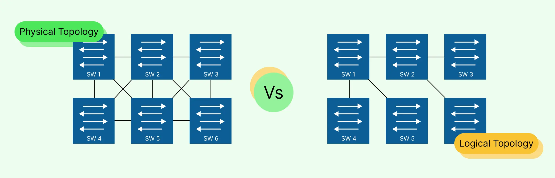
Discover what a logical network diagram is, how it differs from a physical network diagram, why it’s useful, and how to create one.