What Are Actors in Use Case Diagrams?
Actors in a use case diagram represent the roles that interact with a system. They can be individuals, external systems, or organizations that exchange information or perform actions with the system being modeled. Their main purpose is to define who uses the system and what they expect it to do, helping clearly establish boundaries between the system and its environment.
Role of Actors in System Modeling
Actors serve as the starting points for all system interactions. They trigger use cases, exchange information, and receive outcomes. Defining them correctly ensures that system behavior aligns with user needs and real-world workflows.
Why Actors Are Essential in UML
Provide context and perspective to system use cases, defining how users or external systems interact with the system.
Visualize external influence by showing how entities affect system operations and how the system responds to them.
Ensure accurate modeling that reflects real-world scenarios and user interactions.
Facilitate clear communication among stakeholders, designers, and developers by illustrating system boundaries and responsibilities.


Types of Actors in Use Case Diagrams
Primary Actors (Initiates the Use Case)
Primary actors are the main entities that start an interaction with the system to achieve a goal. They represent the end users or external systems that directly benefit from a use case’s outcome.
Examples:
- In an e-commerce system, a Customer initiates the process by placing an order.
- In a banking application, a User initiates a fund transfer.
- In a university portal, a Student registers for a course.
Secondary Actors (Supports System Goals)
Secondary actors assist in completing a use case but do not initiate it. They typically provide services or resources that help the system perform an action, such as authentication servers, databases, or background services.
Examples:
- In an e-commerce platform, a Payment Gateway verifies transactions.
- In a web application, an Email Server sends confirmation emails.
- In a hospital management system, a Database stores and retrieves patient records.
External and Internal Actors
External actors exist outside the system boundary and interact with it to exchange data or perform tasks. Internal actors operate within the system’s environment but are modeled separately to show modular responsibilities, such as subsystems or components.
Examples:
- External actor: A Third-Party API that supplies currency conversion data to a finance app.
- Internal actor: A Reporting Module within an ERP system that interacts with other system components to generate summaries.
Human vs. System Actors
Human actors represent individual users or roles that interact with the system manually (e.g., customers, administrators). System actors, on the other hand, represent automated systems or applications that communicate programmatically, such as APIs, payment gateways, or external databases.
Examples:
- Human actor: An Admin managing user accounts or a Customer browsing products.
- System actor: A CRM System updating customer data or a Notification Service sending alerts automatically.
Read use case diagram tutorial to learn more about use case diagram components and how to use them in diagrams.
How to Identify Actors in Use Case Diagrams
Follow these steps with Creately’s use case diagram tool to easily identify, define, and connect actors with their related use cases, helping you clearly visualize system roles, user interactions, and their relationships.
Step 1: Analyze User Roles and System Interactions
Begin by examining all the entities that interact with your system. Identify users, departments, external systems, or devices that initiate or receive actions. Focus on what each entity wants to achieve rather than their job title or system component. Each unique goal or interaction usually represents a different actor.
Step 2: Ask the Right Questions
Use targeted questions to uncover all relevant actors. These questions help you capture both primary and secondary actors.
- Who uses or benefits from the system?
- What external systems or services communicate with it?
- Who initiates or responds to specific actions?
- Are there supporting systems involved behind the scenes?
- What inputs or outputs does each actor exchange with the system?
Step 3: Categorize the Actors
After identifying all possible actors, organize them into the main types based on their role and relationship with the system. This categorization keeps your use case diagram clear, structured, and easy to interpret.
- Primary actors: Initiate the use case and directly achieve a goal.
- Secondary actors: Support the process or provide necessary services.
- External systems: APIs, software tools, or databases that exchange information.
Step 4: Validate with Real Scenarios
Validate your list of actors by mapping them to real-world scenarios. This step ensures that each actor in your use case diagram represents a genuine interaction and aligns with actual system behavior.
Step 5: Refine and Document
Review the identified actors with your team or stakeholders to confirm accuracy. Document each actor’s role and interaction clearly before adding them to your use case diagram.
By following these steps, you’ll be able to systematically identify all relevant actors in a use case diagram, ensuring your model reflects real-world system interactions and supports effective communication across the team. You can use one of Creately’s ready-made use case diagram templates to get started right away.
Representing Actors in UML Notation
Actor Symbols and Placement
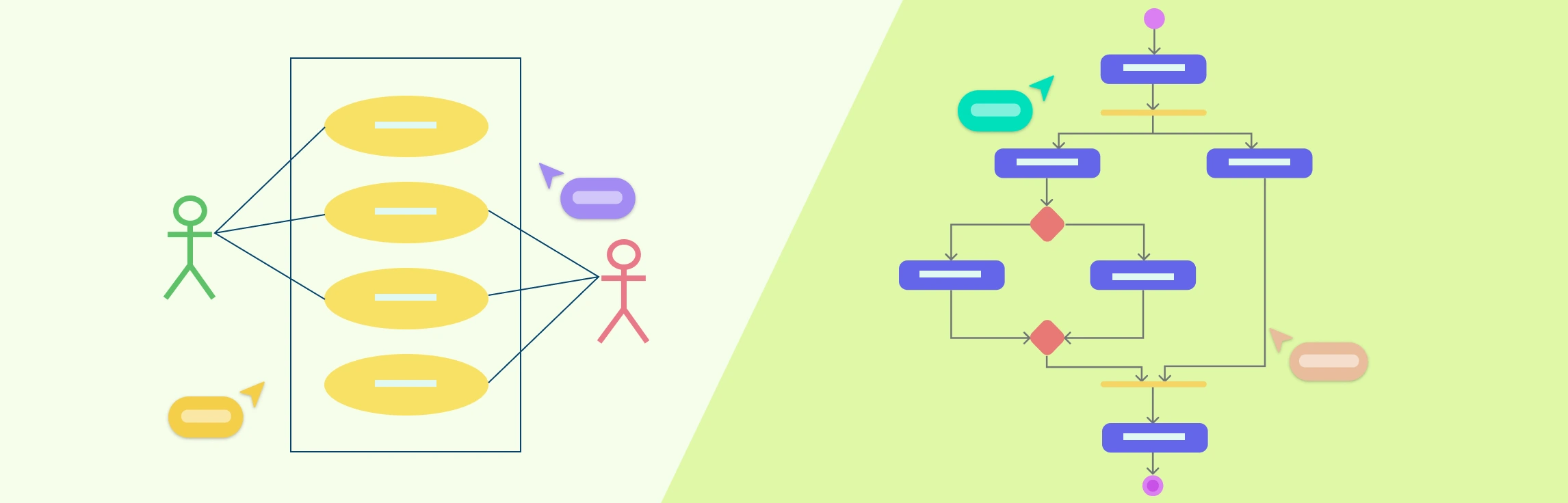
Actors in UML use case diagrams are represented by simple stick figures (or named icons) that depict the role interacting with the system. Actors are placed outside the system boundary (a rectangle representing the system) to clearly distinguish external entities from internal processes. Each actor should be positioned close to the use cases they interact with for readability.
Use Case Symbols
Use cases are represented by oval shapes (ellipses) containing the name of the function or process (e.g., Place Order, Login, Generate Report). These are placed inside the system boundary, showing that they are part of the system’s functionality.
Associations
Solid lines (associations) are drawn between actors and the use cases they participate in. These connections indicate communication or interaction. A single actor can connect to multiple use cases, and multiple actors can connect to the same use case, depending on how they interact with the system.
Relationships
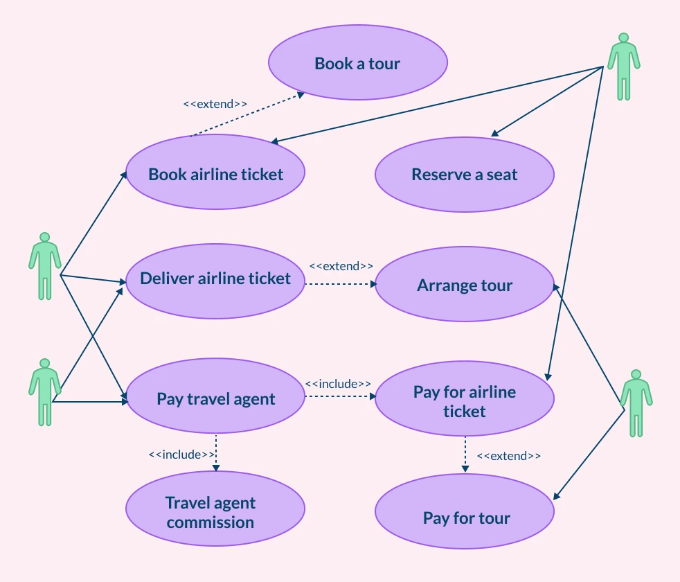
- Association (solid line): Connects actors to the use cases they participate in, representing communication or interaction.
- Include (dashed arrow with «include»): Indicates that one use case always includes the behavior of another.
- Extend (dashed arrow with «extend»): Shows that a use case optionally extends another under specific conditions.
- Generalization (arrow with a hollow triangle): Represents an actor or use case that inherits behavior from a more general one.
The following travel agency use case diagram example illustrates these UML notations in action, showing how actors (such as Customers, Travel Agents, and Payment Systems) interact with various system functions like Book Tickets, Reserve Seats, and Process Payments.
Read use case diagram relationships to learn more about the different types of relationships explained with examples.
Best Practices for Defining Use Case Actors
Keep actors generic yet descriptive: Define actors by their functional role, not by personal names or job titles (e.g., Customer instead of John).
Avoid duplicates or overlapping roles: Merge roles that have identical responsibilities to maintain a clean, logical diagram.
Use clear naming conventions: Label actors consistently using singular nouns that describe what they do (e.g., Administrator, Supplier).
Focus on roles, not people: One person may perform multiple roles, and one role may be filled by different people. Remember to model the role, not the individual.
Limit the number of actors: Include only those who have direct, meaningful interactions with the system to avoid clutter.
Validate each actor’s relevance: Ask, “Does this actor initiate or participate in at least one use case?” If not, it may not belong in the diagram.
Position actors logically: Place primary actors on the left (initiating interactions) and secondary or supporting actors on the right for visual consistency.
Maintain system perspective: Define actors from the system’s viewpoint such as external entities that interact with the system, not components within it.
Do not place actors inside system boundaries: Always position actors outside the system rectangle to preserve the UML standard.
To learn more about making better use case diagrams, read use case diagram guidelines.
Free Use Case Diagram Templates to Get Started


FAQs about Actors in Use Case Diagrams
Can one actor participate in multiple use cases?
Can multiple actors interact with the same use case?
Can an actor be a system?
Is a storage location considered an actor in a use case diagram?
Resources
Evans, Andy, et al. UML 2000 - the Unified Modeling Language: Advancing the Standard. Springer, 29 June 2003.
Ibrahim, Noraini, et al. “On Well-Formedness Rules for UML Use Case Diagram.” Web Information Systems and Mining, 2010, pp. 432–439, https://doi.org/10.1007/978-3-642-16515-3_54.