P&ID Diagram Software
Effortless P&ID Design for Engineers
Streamline process design with Creately’s intuitive piping and instrumentation software. Create precise, standardized diagrams faster and save hours in validation and documentation.
Use ISO and ANSI-compliant symbols to ensure international standard diagrams
Collaborate with your team instantly, wherever you are
Smart diagram tools to streamline alignment, formatting, and connections


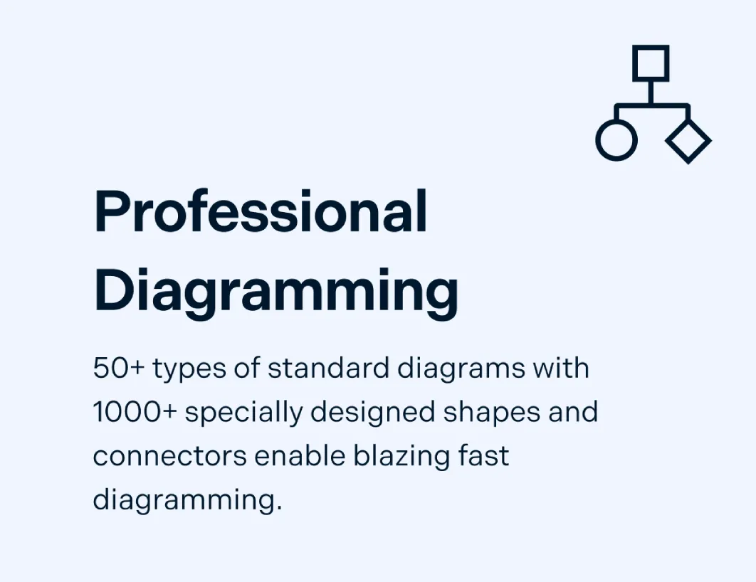
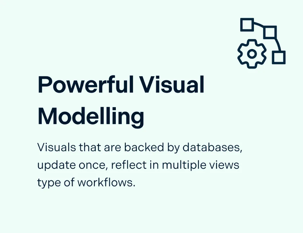
 Diagramming Visual Collaboration Org Chart


Free Pre-Built Piping and Instrumentation Templates
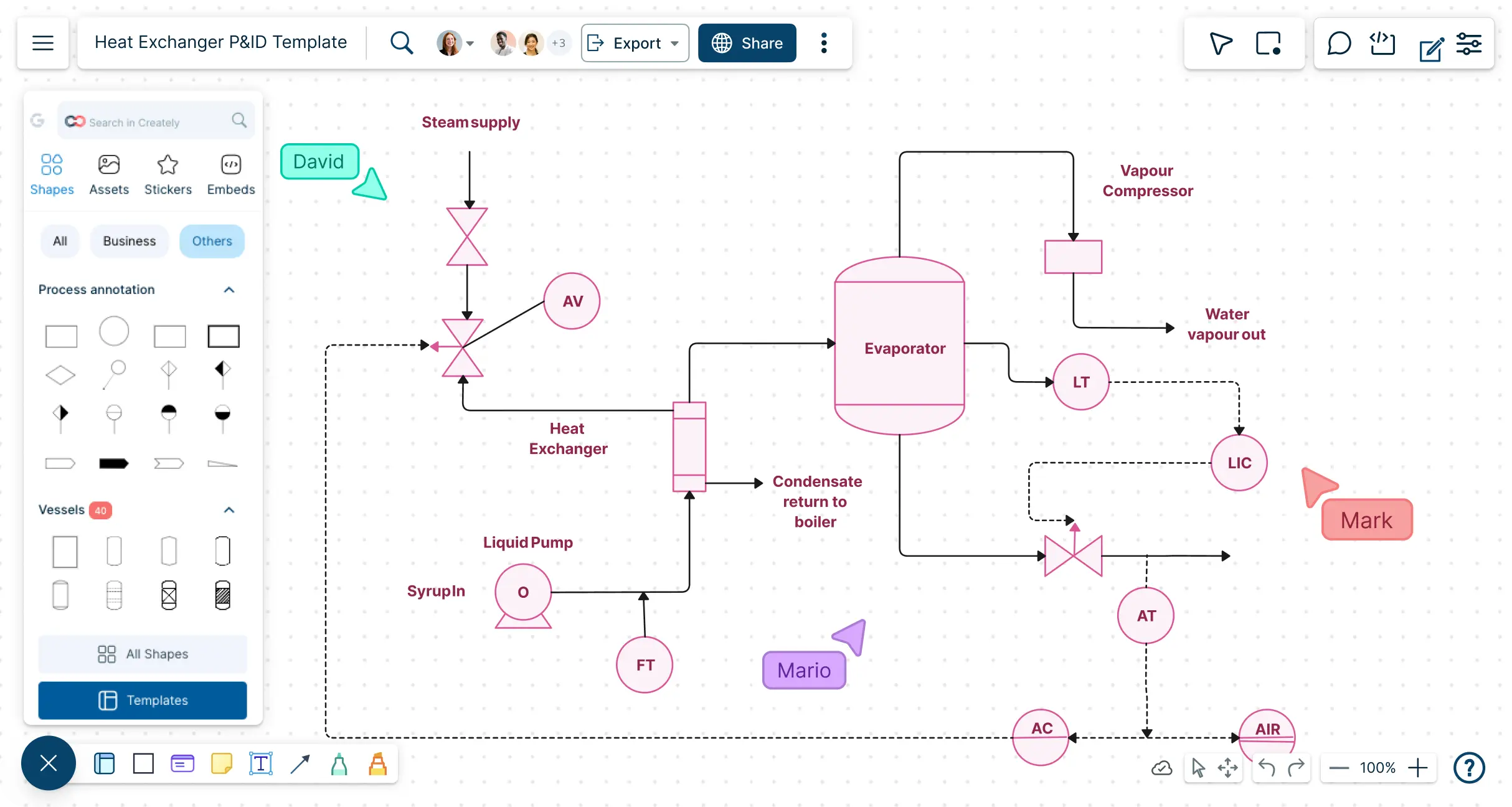
Design and Map Industrial Processes in Minutes

Build accurate P&ID online with pre-loaded industry-standard symbols for valves, pumps, vessels, and instrumentation.
Use drag-and-drop diagramming and smart snapping to speed up layout creation and reduce errors.
Start from ready-made P&ID templates for chemical, mechanical, and industrial processes.
Add notes and annotations to communicate design intent clearly across teams.

Structure Your Piping and Instrumentation Diagrams Efficiently
Auto-align equipment, piping, and control loops for clean, readable diagrams.
Group, layer, and label components to reflect process flow and system hierarchy.
Color code instruments and piping types for quick identification.
Attach datasheets, SOPs, and process documentation for a single source of truth.
Ensure every component is traceable during audits.
Share, Review, and Refine P&ID Diagrams in Real Time

Work side by side with engineers, QA, and maintenance teams in real time, eliminating delays and enabling cross-functional reviews.
Drop comments, annotations, and markups directly on the diagram so feedback is instant and clear.
Share your diagrams easily via links, email, or exports while controlling who can view, comment, or edit with role-based permissions.
Keep every change tracked with version history, making audits and compliance a breeze.

Turn Diagrams into Actionable Workflows for Your Plant
Export diagrams for integration with SCADA, MES, or ERP systems to ensure seamless data flow and operational alignment.
Generate reports and visual documentation for compliance, maintenance, and training.
Update and scale diagrams as processes, equipment, or plant layouts evolve.
Manage large-scale P&ID projects efficiently across teams and facilities.
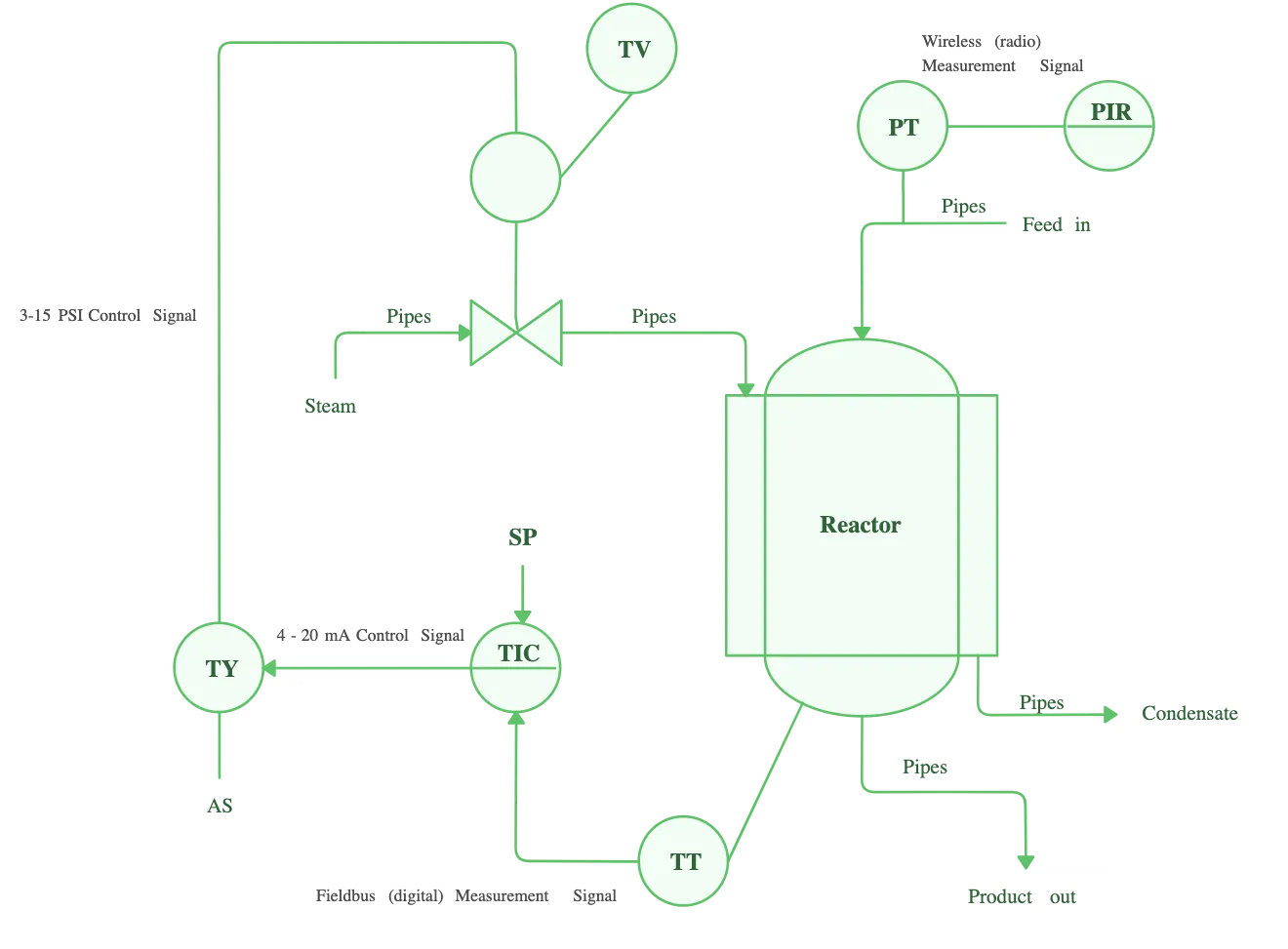
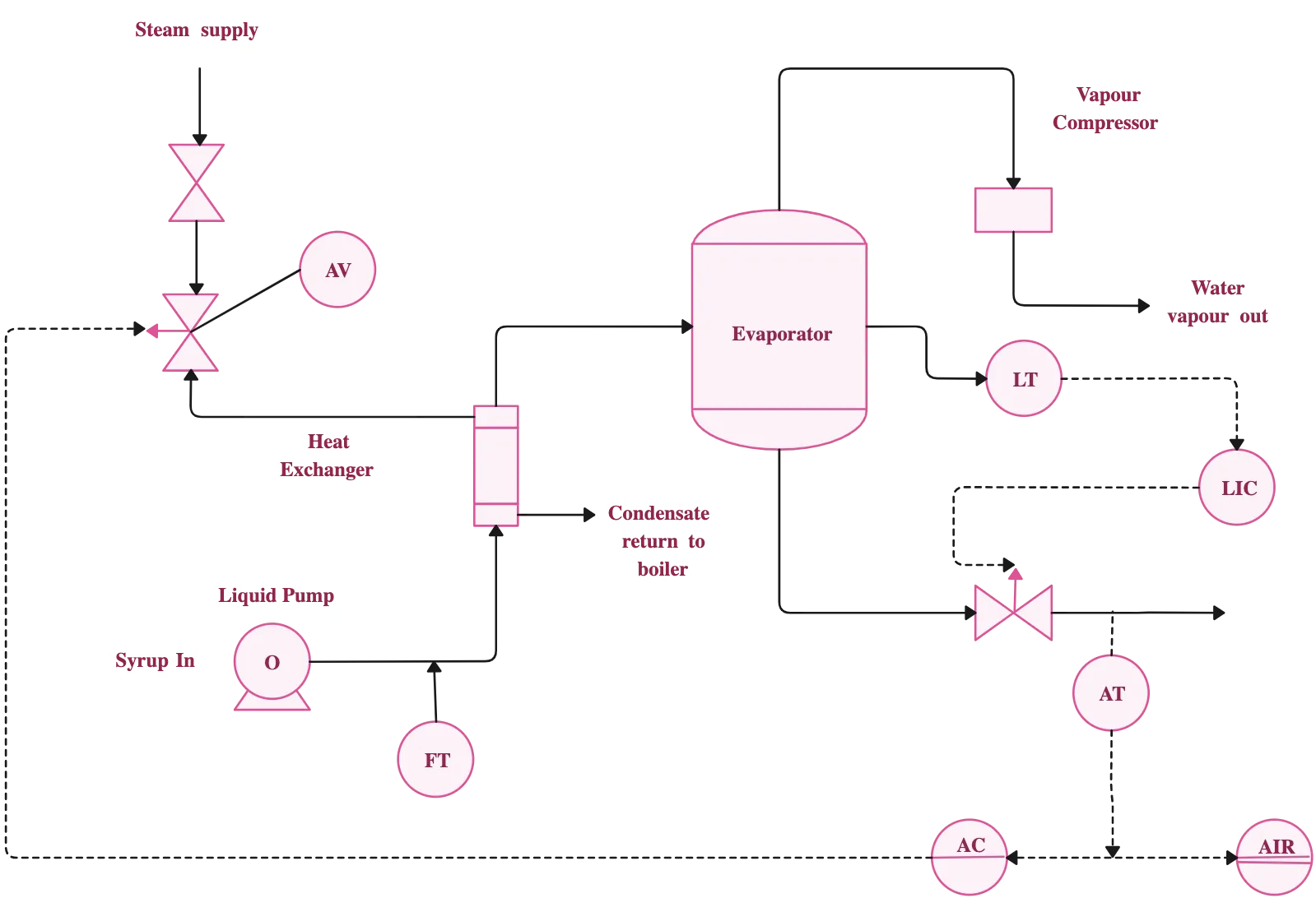
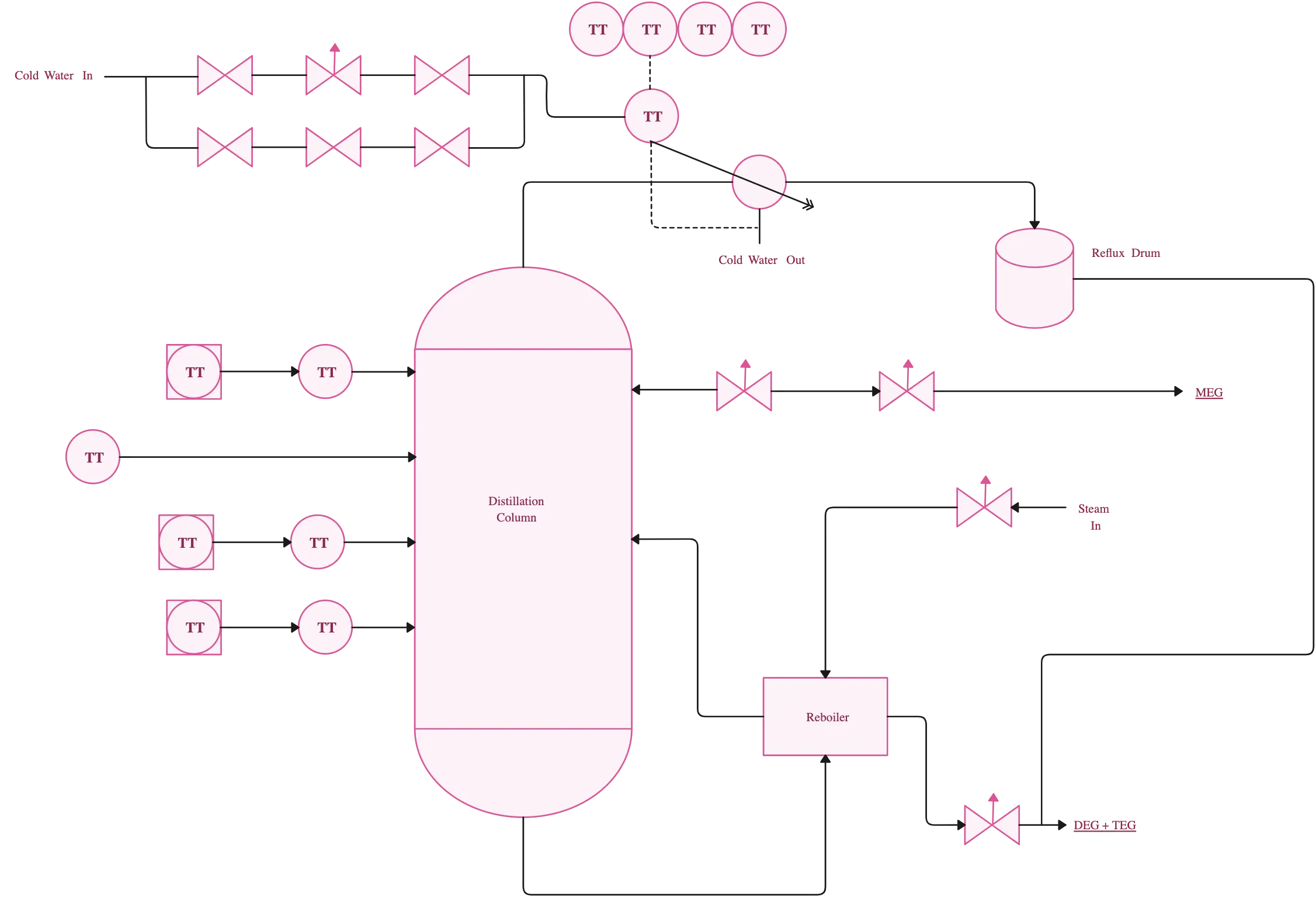
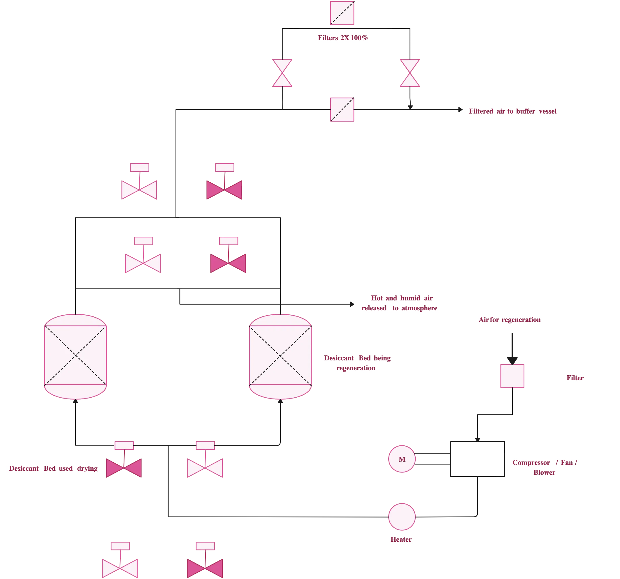
What Is a Piping and Instrumentation Diagram?

How to Draw a P&ID Diagram in Creately
Start with a template or blank canvas
Log in to Creately’s P&ID creator and click “New Diagram”. Choose a P&ID drawing example designed for your industry, such as chemical, mechanical, or industrial processes, or start with a blank canvas to build your diagram from scratch. Templates provide ready-made layouts and symbols, making it faster to get started.
Add equipment and piping components
Open the P&ID shapes library in the P&ID generator and drag valves, pumps, vessels, heat exchangers, and other components onto your canvas. Use smart snapping and alignment guides to position elements neatly and maintain proper connections.
Connect equipment with pipes and flows
Use the P&ID drawing software’s connector tools to draw pipes and flow lines between components. Label each line with flow type or direction, and use color coding to distinguish between process lines, utilities, and control loops for easy readability.
Include instrumentation and annotations
Add sensors, transmitters, and control devices from the shapes panel. Enhance clarity by attaching notes, datasheets, or specifications to components so that every team member understands the purpose and function of each element.
Collaborate, review, and share
Invite your team to Creately’s P&ID maker to edit and comment in real time, ensuring feedback is clear and immediate. Use role-based permissions to control access, track all changes with version history, and export your diagram in PDF, PNG, or SVG formats for documentation, presentations, or integration with other systems.
Create a P&ID DiagramFAQs About Creately’s P&ID Drawing Software
What are the benefits of Creately’s P&ID Diagram Software?
Detect bottlenecks and potential conflicts in your P&ID diagrams.
Simulate flow paths and control loops to test design changes.
Visualize dependencies between equipment, instrumentation, and piping systems.
Make data-driven decisions with diagram-based insights.
Create accurate, professional diagrams quickly and efficiently.
What standardized P&ID shapes and symbols does Creately support?
In what other ways can engineers use Creately?
Who can use Creately’s P&ID software?
Process, mechanical, and chemical engineers.
Piping designers and instrumentation specialists.
Operations and maintenance teams.
Engineering students and educators for training purposes.
When should I use P&ID software?
During the design phase of process systems.
To document existing piping and instrumentation setups.
For troubleshooting, maintenance planning, and process optimization.
When standardizing diagrams across teams or facilities.
Does Creately support industry-standard symbols?
Yes, it provides ISO and ANSI-compliant symbols for pumps, valves, vessels, instruments, and more.
Symbols are organized in an easy-to-use library for fast access.
Custom symbols can be added to match specific project requirements.
Can I share or export my P&ID diagrams?
Diagrams can be shared via links, email, or team workspaces.
Export options include PDF, PNG, SVG, and other formats for presentations or documentation.
Creately integrates with Confluence and other project management or documentation tools for seamless collaboration.
What is the best tool for drawing P&ID diagrams?