When designing a database, the relationships between entities are just as important as the entities themselves. Among these, one-to-many relationships are the most commonly used and foundational in building scalable, logical, and normalized data models. This guide explains what one-to-many relationships in ER diagrams are, how to represent them using different notations, how to identify them correctly during data modeling, and why they matter in real-world database design. This will help you understand how ERD relationships shape a database system’s overall structure and efficiency.
What Is a One-to-Many Relationship?
One-to-many relationships in ER models are one of the most fundamental concepts in data modeling. An Entity-Relationship (ER) model is a visual framework used to map out how different data entities relate to each other. Understanding how these relationships work—especially 1-to-many relationships—is key to designing clear, efficient databases.
Defining One-to-Many Relationships
A one to many relationship describes a situation where one record in a table can be associated with many records in another. For instance, one customer can place many orders, or one department can have many employees. These relationships are common and necessary in real-world systems.
In ER diagrams, one-to-many relationships are usually shown with a straight line ending in a “crow’s foot,” which represents the “many” side. This kind of relationship ensures data is stored efficiently and reflects how entities interact in real-world business processes.
By accurately identifying and mapping one-to-many relationships in ER models, you can improve data organization, minimize redundancy, and build databases that scale smoothly with growing information.
How to Show One-to-Many Relationships in ER Diagrams in Different Notations
When working with Entity-Relationship models, it’s essential to understand how one-to-many relationships are visually represented. The ER diagram not only communicates how entities are related but also helps ensure clarity in the database structure. There are standard ER diagram symbols and notations that are used to draw these entity relationships. Knowing the right notations makes it easier to read, interpret, and design effective ER diagrams.
To illustrate one-to-many relationships in various ER diagram notations, here’s a comparative overview of how this relationship is represented in Chen, Crow’s Foot, and UML notations:
Example:
- Entities: Customer, Order
- Relationship: Places
The entity, Customer, is connected to the entity, Order, through the Places relationship.
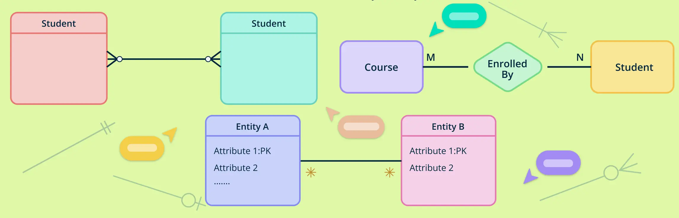
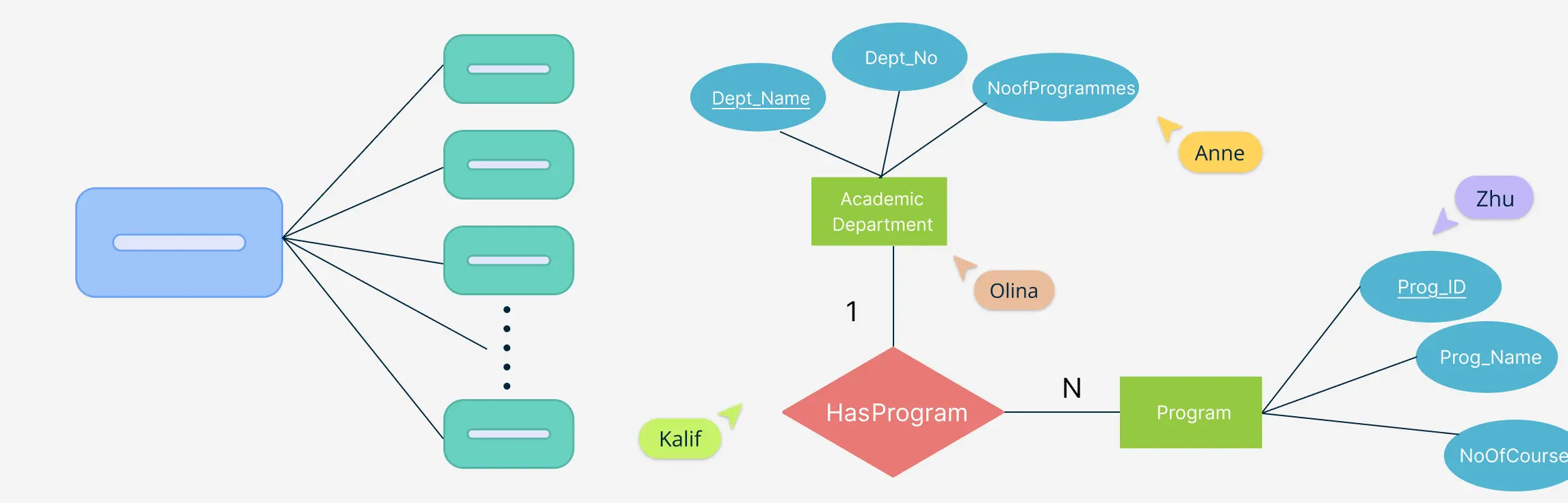
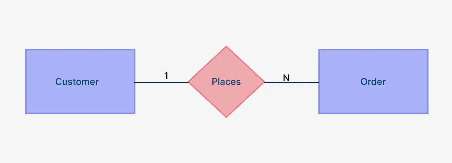
Chen Notation
In Chen notation, entities are depicted as rectangles, and relationships are shown as diamonds connecting these entities.
- A “1” near the entity on the “one” side.
- An “N” near the entity on the “many” side.
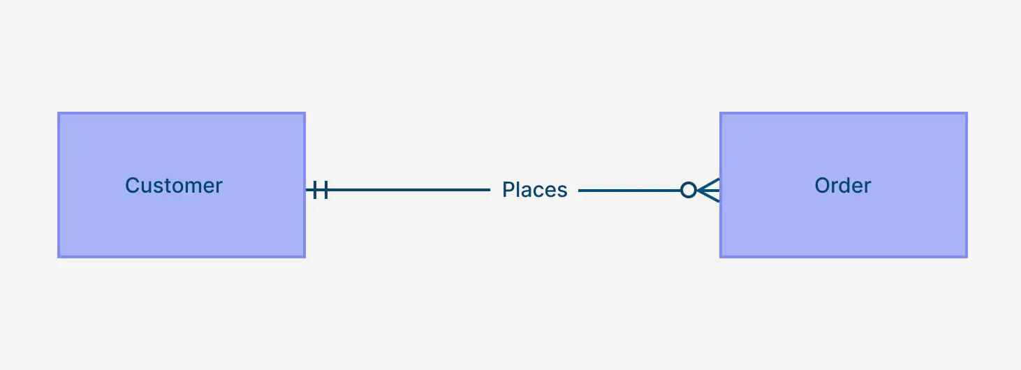
Crow’s Foot Notation
Crow’s Foot notation uses symbols at the ends of relationship lines to denote cardinality. A one-to-many relationship is depicted with:
- A straight line ending (|) at the “one” side.
- A three-pronged “crow’s foot” at the “many” side.
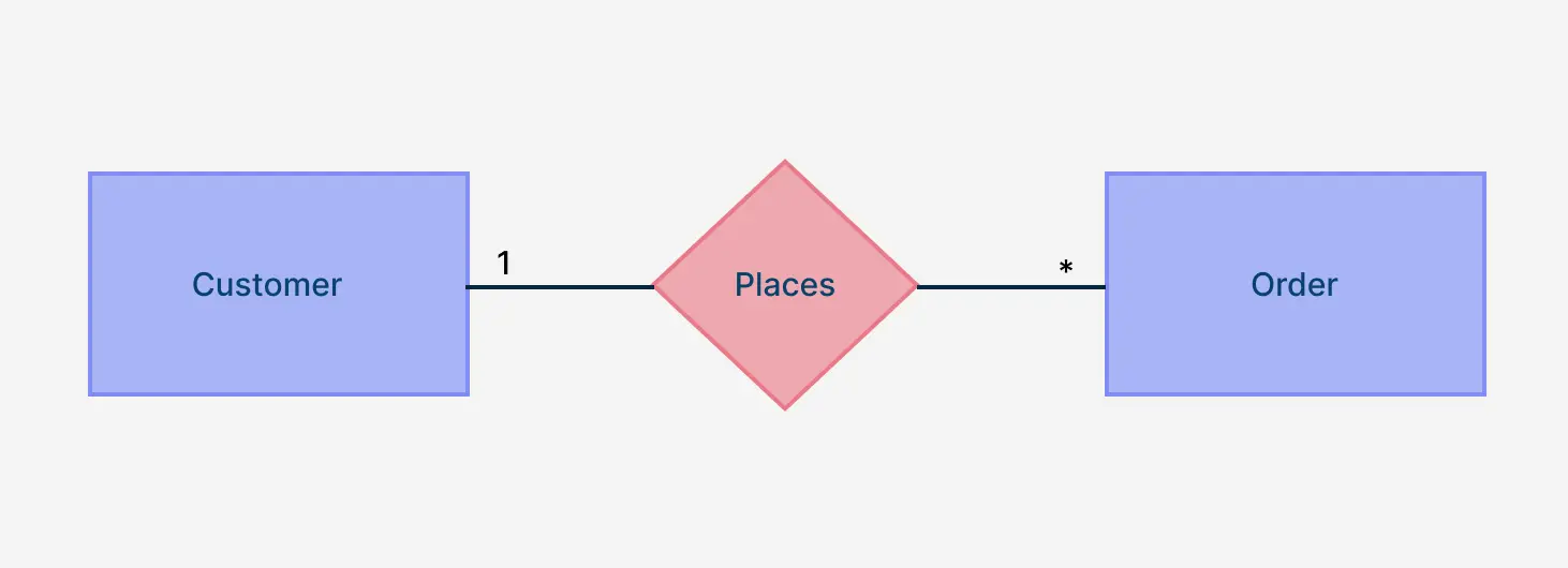
UML Notation
In Unified Modeling Language (UML), relationships are shown as lines connecting classes (entities), with multiplicity indicators at each end.
- “1” near the class on the “one” side.
- “*” (asterisk) near the class on the “many” side.
These notations provide different visual approaches to represent one-to-many relationships in ER diagrams. Depending on the context and audience, you can choose the notation that best conveys the relationship structure in your database design.
Examples of One-to-Many Relationships in ER Diagrams
One-to-many relationships are everywhere in real-world database applications. From education to transportation, these relationships form the structural core of how data is organized and connected in different systems. Below are several practical examples that illustrate how one-to-many relationships in ER diagrams work across various industries.
1. Education Systems
In educational databases, a one-to-many relationship typically connects a teacher to multiple students.
- Entities: Teacher, Student
- Relationship: One teacher teaches many students.
- This is modeled by linking the
teacher_idfrom the Teacher table as a foreign key in the Student table.


Read more: 10 ER Diagrams for a University Management System + Free Templates
2. Healthcare Systems
Hospitals and clinics use one-to-many relationships to manage patient records.
- Entities: Doctor, Patient
- Relationship: One doctor treats many patients.
- In an ER diagram, the doctor’s ID serves as the primary key, while the patient table holds it as a foreign key.


Read more: 10 ER Diagrams for Hospital Management Systems + Free Templates
3. Retail & Shopping Systems
In e-commerce or retail systems, the relationship between customers and orders is a classic example.
- Entities: Customer, Order
- Relationship: One customer places many orders.
- This setup helps track purchase history and generate reports.


4. Transport & Reservation Systems
Travel databases use one-to-many relationships to link schedules and bookings.
- Entities: Bus, Ticket or Flight, Reservation
- Relationship: One bus or flight has many tickets or reservations.
- The transport entity’s ID becomes a foreign key in the booking table.


5. Library & Information Systems
Library databases often model a one-to-many relationship between books and borrowers.
- Entities: Member, Borrowed Book
- Relationship: One member can borrow many books.
- This helps in tracking borrow history and due dates.


Read more: ER Diagram for Library Management System + Free Templates
6. Administrative & Organizational Systems
In HR or organizational databases, a department often has many employees.
- Entities: Department, Employee
- Relationship: One department oversees many employees.
- The department ID is a foreign key in the employee records.


Read more: 6 ER Diagrams for Employee Management System + Free Templates
These real-life examples highlight how essential one-to-many relationships are in designing scalable and efficient databases. Properly representing these relationships in your ER diagrams ensures both logical structure and data integrity.
How to Identify One-to-Many Relationships in Data Modeling
Identifying one-to-many relationships is a foundational step when designing an Entity-Relationship Diagram (ERD). These relationships are not always obvious at first glance, especially when starting from a list of business rules, forms, or existing workflows. Recognizing them early ensures your data model reflects real-world logic and supports future scalability.
To identify a one-to-many relationship while building an ERD, ask these key questions about your data:
- Does one instance of Entity A relate to multiple instances of Entity B?
- Can Entity B records exist independently, or do they depend on Entity A?
- Is there a repeating group or list of items tied to a single subject or entity?
These patterns often reveal one-to-many relationships. For example:
- In a sales system, one customer places many orders.
- In a university system, one course enrolls many students.
- In an HR system, one manager oversees many employees.
If the answer to these questions points to repeated associations from one record to many, you’re likely looking at a one-to-many relationship.
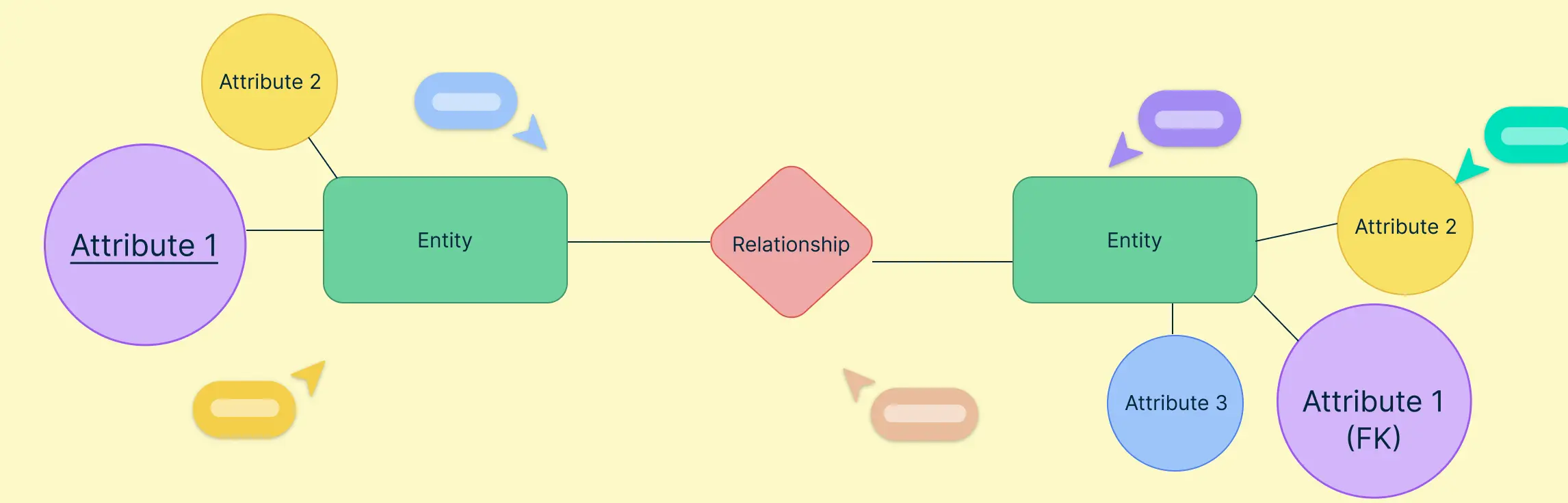
Characteristics of One-to-Many Relationships
In one-to-many relationships, one entity contains a unique record that connects to several related records in another entity. Typically, you’ll observe the following:
- The “one” side has a primary key—a unique identifier for each record.
- The “many” side includes a foreign key that references the primary key in the “one” entity.
For example, in a school database:
- One teacher can teach many students.
- The Teacher table has a primary key (e.g.,
teacher_id). - The Student table uses
teacher_idas a foreign key.
This structure maintains data consistency and allows easy querying across related tables.
Comparing with Other Relationships
It’s important to distinguish one-to-many relationships from other types:
- One-to-one relationship: Each record in one entity is related to only one record in another.
- Example: One person ↔ One passport.
- Many-to-many relationship: Multiple records in one entity relate to multiple records in another, often requiring a junction table.
- Example: Students ↔ Courses.
By identifying these patterns during data modeling, developers can apply the correct relationship structure and ensure that the database reflects real-world logic.
Why One-to-Many Relationships Matter in Database Design
Understanding and correctly applying one-to-many relationships in database design is essential for building systems that are both efficient and scalable. These relationships form the backbone of most relational databases, making it easier to store, retrieve, and maintain structured data across various applications.
Performance Benefits of One-to-Many Relationships
Well-modeled one-to-many relationships improve performance by reducing data duplication. When a single entity is related to many others, using a primary key–foreign key structure allows databases to run faster queries and perform joins more efficiently. Instead of repeating information across multiple rows, relational links keep the data normalized and compact.
Enhancing Data Integrity
One-to-many relationships help maintain data integrity by enforcing logical connections between related tables. For example, if a customer places multiple orders, those orders must link back to a valid customer ID. Using foreign keys ensures that records in the “many” side (like Orders) cannot exist without a corresponding entry in the “one” side (like Customers). This prevents orphaned records and maintains consistency across the database.
Role in Normalization
Normalization—the process of organizing data to reduce redundancy—relies heavily on one-to-many relationships. These relationships enable database designers to split complex data into multiple tables while maintaining logical connections. Instead of storing all customer and order data in a single table, normalization separates them and links them through a one-to-many relationship, creating a cleaner, more maintainable structure.
In other words, properly identifying and implementing one-to-many relationships in ER design ensures your database is fast, accurate, and built for long-term scalability.
Best Practices for Modeling One-to-Many Relationships
When working with one-to-many relationships in ER modeling, the accuracy of your database structure depends heavily on how well these relationships are defined and implemented. While the concept may seem straightforward, there are several pitfalls that can compromise the performance and reliability of your data model. At the same time, following industry best practices can help you build clear, consistent, and scalable ER diagrams.
1. Correctly Identifying Relationship Cardinality
One of the most frequent mistakes in modeling one-to-many relationships is confusing them with one-to-one or many-to-many relationships. This leads to flawed entity connections, resulting in data anomalies or inefficient queries. Always assess real-world business rules to define the correct relationship cardinality.
2. Well-Structured Keys
Using non-unique or unstable values as primary or foreign keys can break one-to-many relationships. The “one” side must have a reliable primary key, while the “many” side should reference it with a proper foreign key. Avoid using compound keys unless absolutely necessary.
3. Keeping Referential Integrity
Failing to enforce referential integrity leads to broken links and orphaned records. Always define foreign key constraints to ensure that every related record in the “many” table points to a valid record in the “one” table. This safeguards your data consistency.
4. Use Clear and Consistent Naming Conventions
Use intuitive, self-explanatory names for tables and columns. For example, a foreign key like customer_id in the Orders table should clearly indicate its relationship to the Customers table. This makes your one-to-many relationships easier to read and maintain.
5. Maintain a Consistent Schema Design
Consistency across your schema helps avoid confusion. Standardize how you structure entities, define primary and foreign keys, and represent relationships in diagrams. This is especially important when teams collaborate across different modules or systems.
6. Leverage Professional Diagramming Tools
Modern ER diagram tools make it easier to design and manage one-to-many relationships visually. These platforms also support different notations such as Crow’s Foot and UML, helping you clearly define one-to-many relationships in ER diagrams with accuracy and clarity. A versatile ER diagram maker offers intuitive drag-and-drop interfaces, relationship templates, and real-time collaboration.
Helpful Resources
Discover ER diagram usage, history, symbols, notations and more.
Quickly create your ER diagrams online, collaborate with your team, maintain and track changes as the design evolves.
Design and visualize database schema with Creately's Entity Relationship Diagram templates.
Find out what Crow’s Foot Notation is, and explore how they bring clarity to the intricate world of entities, attributes, and relationships.
Learn how to illustrate many-to-many relationships in ER diagrams using best practices
Conclusion: Mastering One-to-Many Relationships for Smarter Database Design
One-to-many relationships are the backbone of effective database modeling, enabling accurate data structuring, integrity enforcement, and scalable design. In this guide, you’ve learned how to define and identify one-to-many relationships in ER diagrams, explored how they work in real-world systems, and uncovered best practices to avoid common pitfalls.
Ready to apply this knowledge to your own data modeling projects? Use Creately to easily map out your one-to-many relationships, collaborate in real time, and visualize complex systems without the hassle. Start creating smarter, cleaner, and more efficient databases today.
FAQs About One-to-Many Relationships
Can a one-to-many relationship exist within the same table?
manager_id values that point to another employee record. One manager can relate to many subordinates, so the relationship remains one-to-many within a single entity.Are one-to-many relationships always mandatory in database design?
How do one-to-many relationships affect data retrieval performance?
Resources:
Frantiska, J. (2017). Entity-Relationship Diagrams. Visualization Tools for Learning Environment Development, pp.21–30. doi:https://doi.org/10.1007/978-3-319-67440-7_4.
Pigott, D.J. and Hobbs, V.J. (2011). Complex knowledge modelling with functional entity relationship diagrams. VINE, 41(2), pp.192–211. doi:https://doi.org/10.1108/03055721111134817.