Many-to-many relationships are a fundamental concept in Entity-Relationship (ER) modeling. They represent scenarios where multiple instances of one entity can be associated with multiple instances of another. In this guide, you’ll learn how to illustrate many-to-many relationships in ER diagrams using best practices.
We’ll cover everything from what these relationships mean to how they’re represented, and even walk through a practical example to bring the concept to life. Whether you’re new to ER diagrams or refining your data modeling skills, understanding many-to-many relationships is key to creating precise and scalable database designs.
What Are Many-to-Many Relationships?
In database design, many-to-many relationships describe a situation where multiple records in one entity are associated with multiple records in another entity. This type of relationship is common in real-world systems where both sides of the relationship can have numerous associations.
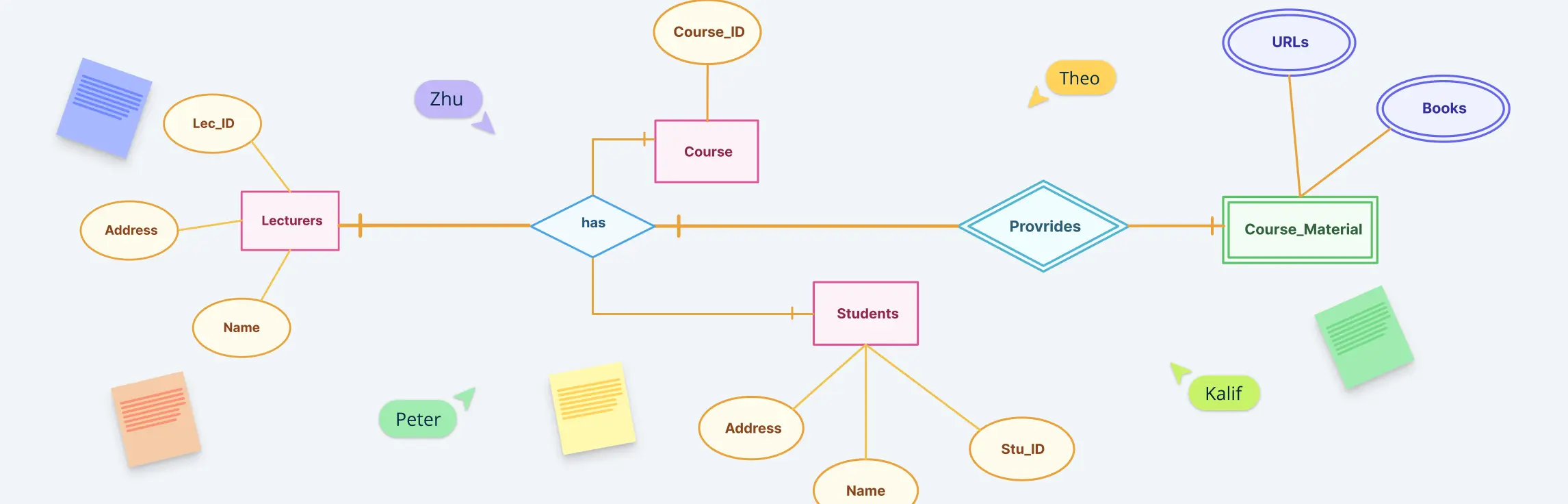
For instance, think about a system with students and courses. A student can enroll in several courses, and each course can have many students enrolled. This is a textbook example of a many-to-many relationship—neither side is limited to a single connection, making it necessary to model this structure accurately within an ER diagram.


Normalization: The Key to Handling Many-to-Many Relationships
Unlike one-to-one or one-to-many relationships, many-to-many relationships require an intermediary or associative entity to represent the complexity of these connections effectively. This process is called normalization. Without this, the data model would be incomplete or misleading, which could result in flawed database behavior.
To normalize a many-to-many relationship, an associative entity (also known as a junction or linking table) is introduced. This intermediary table breaks the direct many-to-many connection into two one-to-many relationships.
For example, instead of directly connecting [Students] and [Courses], an [Enrollments] table is used to link them, resulting in:
- One student can have many enrollments
- One course can have many enrollments
This normalized structure avoids data duplication, ensures consistency, and makes the database easier to query and maintain. In fact, identifying and resolving many-to-many relationships through normalization is one of the primary reasons R diagrams are created in the first place, to help uncover hidden relationships and design a reliable database schema.

Understanding many-to-many relationships is critical because they reflect the flexible, interconnected nature of real-world data. When illustrated properly in ER diagrams, they help ensure that your database captures all relevant relationships without loss of detail or functionality.
Many-to-Many Relationships in ER Notation
Understanding how to read and draw many-to-many relationships in ER diagrams starts with recognizing the correct notation. These relationships are represented using specific ER Diagram symbols and structures that help communicate how entities relate to one another within a system.
Crow’s Foot Notation
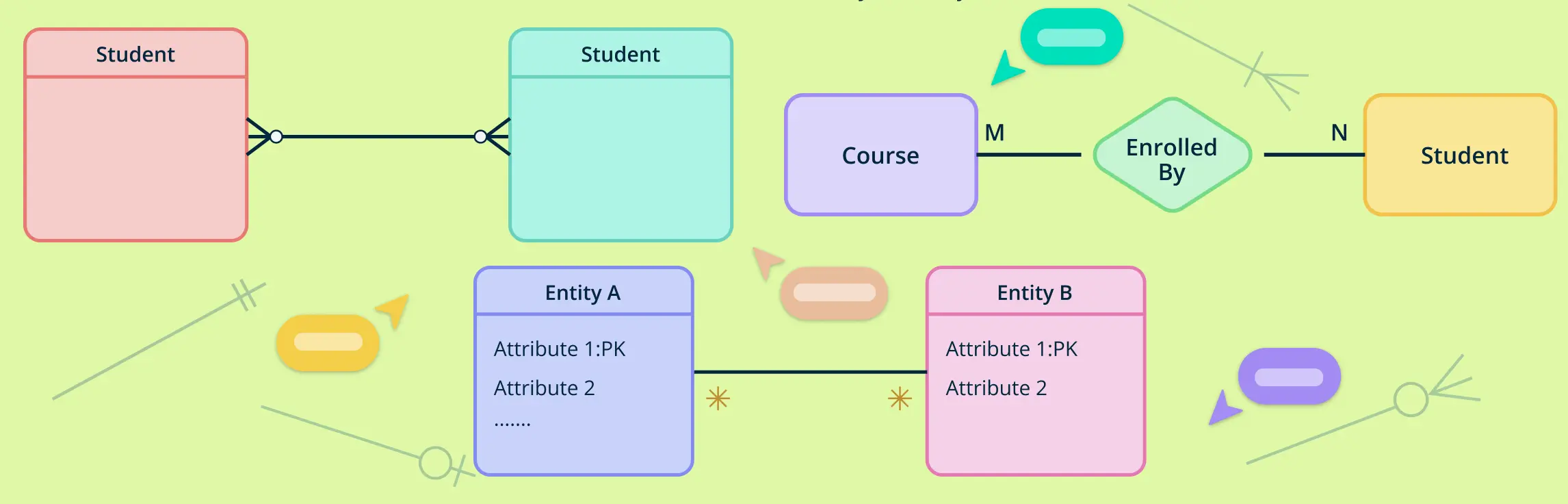
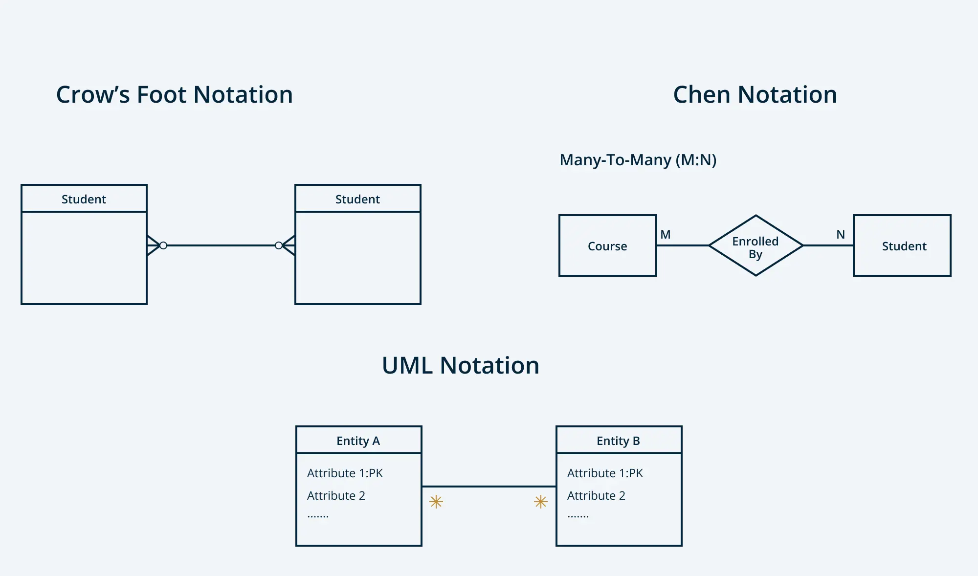
In crow’s foot ER diagrams, many-to-many relationships are denoted by a straight line connecting two entities, with a crow’s foot (three-pronged symbol) at both ends of the line. This indicates that each entity can be associated with multiple instances of the other.
Chen Notation
In Chen notation, many-to-many relationships are represented using diamonds to denote the relationship itself. The entities are shown as rectangles, and the relationship (the diamond) connects them using straight lines.
To explicitly indicate cardinality, the notation places M:N or many-to-many near the connecting lines on both sides of the diamond. This helps clearly define the nature of the relationship between the two entities.
UML Notation
In UML class diagrams, many-to-many relationships are depicted by connecting two classes (entities) with a straight line, and adding multiplicities near each end of the line. The multiplicity * (asterisk) indicates “many.”
Despite stylistic differences, the core concept of many-to-many relationships remains the same—both entities can have multiple related instances of the other.
How to Show Many-to-Many Relationships in ER Diagrams
Illustrating many-to-many relationships in ER diagrams involves a few essential steps. Since many-to-many connections can’t be directly represented with a single relationship line in most database systems, a third entity—often called a junction or associative entity—is introduced to manage the connection.
Step 1: Identify the Two Main Entities
Start by identifying the two entities involved in the many-to-many relationship. For example, in a university database, the two entities might be Students and Courses. Both entities should have a primary key to uniquely identify each record.
Step 2: Recognize the Many-to-Many Nature
Verify that each instance of Entity A can be related to multiple instances of Entity B, and vice versa. If this condition holds, you’re dealing with a many-to-many relationship. Using the same example, one student can enroll in multiple courses, and each course can have many students.
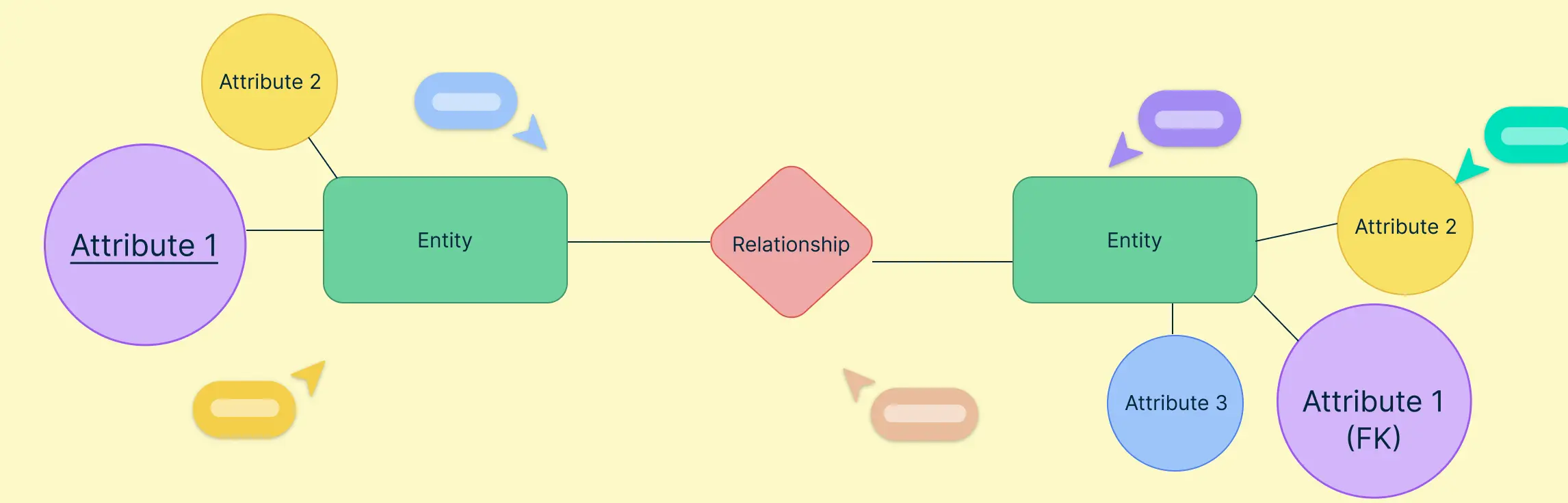
Step 3: Create an Associative Entity
Since direct many-to-many relationships can’t be implemented in most relational databases, you’ll need to create an intermediate entity, commonly known as a junction table or associative entity. This new entity will contain foreign keys referencing the primary keys of the original two entities.
For instance:
- Entity A: Students
- Entity B: Courses
- Associative Entity: Enrollments
The Enrollments table holds the foreign keys from both Students and Courses. It captures the many-to-many relationship by breaking it down into two one-to-many relationships.
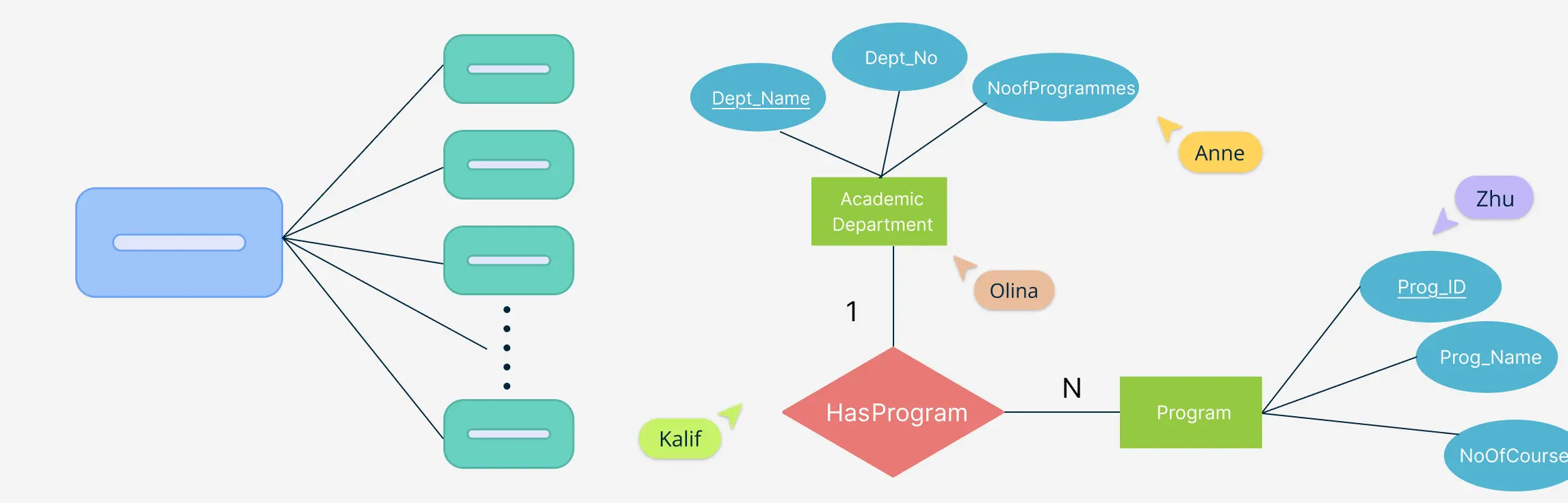
Step 4: Connect Entities with Correct Cardinality
In your ER diagram:
- Draw a relationship from Entity A to Entity B with a one-to-many cardinality. This would be from Students to Enrollments in the example.
- Do the same from Entity B to the Associative Entity, that is Courses to Enrollments in the example.
This setup visually and structurally represents the original many-to-many relationship in a way that aligns with database design best practices.
Step 5: Add Attributes to the Associative Entity (If Needed)
If there are attributes specific to the relationship itself—like enrollment_date or grade in our example—they should be added to the associative entity (Enrollments), not to the original entities. This keeps the model clean and logical.
Examples of a Many-to-Many Relationship in an ER Diagram
Many-to-many relationships appear frequently in real-world systems, especially in environments where multiple entities interact dynamically with one another. In ER diagrams, these relationships require special attention to ensure they’re modeled correctly with associative entities. Below are several common examples, categorized by domain, to show where and how many-to-many relationships typically occur.
1. Education Systems
Education-related databases often involve students, courses, instructors, and classes—all of which commonly share many-to-many relationships.
- Example: In a university system, students enroll in multiple courses, and each course is attended by multiple students.
Many-to-Many Entities:Students↔Courses
Associative Entity:Enrollments


Read more: 10 ER Diagrams for a University Management System + Free Templates
2. Healthcare Systems
Hospitals and clinics manage complex relationships between patients, doctors, rooms, and treatments, many of which are many-to-many.
- Example: Doctors can attend to multiple patients, and patients can be treated by multiple doctors.
Many-to-Many Entities:Doctors↔Patients
Associative Entity:AppointmentsorTreatments


Read more: 10 ER Diagrams for Hospital Management Systems + Free Templates
3. Retail & Shopping Systems
E-commerce and retail management platforms often involve products, customers, orders, and shopping carts, where many-to-many relationships are essential.
- Example: Customers can place multiple orders, and each order can include multiple products.
Many-to-Many Entities:Orders↔Products
Associative Entity:Order_ItemsorCart_Items


4. Transport & Reservation Systems
Systems that manage reservations or rentals typically feature many-to-many connections between users and services.
- Example: Passengers can book multiple flights, and each flight has multiple passengers.
Many-to-Many Entities:Passengers↔Flights
Associative Entity:Reservations


5. Library & Information Systems
Libraries manage books, borrowers, and loans, often structured as many-to-many relationships.
- Example: A book can be borrowed by many users, and users can borrow many books.
Many-to-Many Entities:Users↔Books
Associative Entity:Loans


Read more: ER Diagram for Library Management System + Free Templates
6. Administrative & Organizational Systems
Complex staff and service management structures also rely on many-to-many modeling.
- Example: Employees may work on multiple projects, and each project can involve multiple employees.
Many-to-Many Entities:Employees↔Projects
Associative Entity:Assignments


Read more: 6 ER Diagrams for Employee Management System + Free Templates
These examples highlight how many-to-many relationships form the backbone of accurate, scalable ER models. Properly illustrating them ensures your database design mirrors the true complexity of your system.
Why Many-to-Many Relationships Matter in ER Modeling
Many-to-many relationships play a critical role in accurately modeling how entities interact in complex systems. When not represented correctly, they can lead to data inconsistencies, limited functionality, and poor scalability. This section explains why properly illustrating many-to-many relationships in ER diagrams is essential for building reliable, efficient, and future-proof databases.
1. Capturing Real-World Complexity
Many-to-many relationships are common in ER modeling because they accurately reflect how entities interact in real-world systems. Most real-life scenarios involve entities that can be linked to multiple other entities. For example, a teacher can teach several classes, and each class can be taught by several teachers. Ignoring or simplifying these relationships can lead to inaccurate data models that fail to meet user needs.
2. Preventing Data Redundancy and Inconsistencies
Illustrating many-to-many relationships correctly helps avoid data redundancy and inconsistencies. Without using a junction table or associative entity, there’s a risk of repeating data across tables, which can make updates more difficult and increase the likelihood of data inconsistencies.
For instance, storing course enrollments directly in the student or course table would lead to duplicated rows and make it harder to manage additional details like enrollment dates or grades.
3. Enabling Scalable and Flexible Database Design
Proper representation of many-to-many relationships supports scalable database structures. As data grows—whether through more students, courses, or enrollments—a well-structured model using an associative entity ensures the system remains efficient and easy to maintain. It also simplifies queries, data integrity enforcement, and future expansions.
4. Supporting Advanced Features and Analytics
When many-to-many relationships are clearly defined in ER diagrams, they open up opportunities for deeper analytics. You can easily track user behavior, analyze interactions between entities, and build features based on complex relationships—all without restructuring the database later.
Helpful Resources
Discover ER diagram usage, history, symbols, notations and more.
Quickly create your ER diagrams online, collaborate with your team, maintain and track changes as the design evolves.
Design and visualize database schema with Creately's Entity Relationship Diagram templates.
Find out what Crow’s Foot Notation is, and explore how they bring clarity to the intricate world of entities, attributes, and relationships.
Explore what they are, how to identify and illustrate them correctly during data modeling.
Conclusion
Understanding and correctly illustrating many-to-many relationships is a vital part of effective ER modeling. These relationships appear in a wide range of systems—from education and healthcare to e-commerce and employee management—making them essential for accurate database design.
In this guide, we explored what many-to-many relationships are, why they matter, and how to illustrate them properly in ER diagrams using associative entities. We also looked at real-world examples and categorized templates where many-to-many relationships are commonly used.
By modeling these relationships correctly, you ensure that your ER diagrams reflect real-world interactions accurately, prevent data inconsistencies, and create a foundation for scalable, efficient database systems. Mastering how to illustrate many-to-many relationships in ER diagrams is a skill every database designer and developer should have. Creately, with its many diagramming and collaboration tools, enables you to create ER diagrams easily and efficiently.
FAQs About Many-to-Many Relationships
What is a many-to-many identifying relationship?
Why is it important to resolve many-to-many relationships in ER diagrams?
What is the difference between one-to-many and many-to-many relationships in ER diagrams?
Why is it important to resolve many-to-many relationships in ER diagrams?
When should you use a many-to-many relationship in ER modeling?
Why can’t databases handle many-to-many relationships directly?
Resources:
Frantiska, J. (2017). Entity-Relationship Diagrams. Visualization Tools for Learning Environment Development, pp.21–30. doi:https://doi.org/10.1007/978-3-319-67440-7_4.
Pigott, D.J. and Hobbs, V.J. (2011). Complex knowledge modelling with functional entity relationship diagrams. VINE, 41(2), pp.192–211. doi:https://doi.org/10.1108/03055721111134817.