When designing a relational database, understanding how entities connect is just as important as defining the entities themselves. That’s where the foreign key in ER diagrams comes in. It serves as the critical link that binds different tables together, helping you create a structured, meaningful database model.
In this guide, we’ll explore what a foreign key is, how it’s represented in an ER diagram, and why it matters. Whether you’re a student, developer, or database designer, this guide will walk you through everything you need to know.
What Is a Foreign Key in ER Diagrams?
A foreign key is a field (or collection of fields) in one table that refers to the primary key in another table. This connection defines a relationship between two tables, ensuring that the data remains consistent across the database, known as referential integrity.
In the context of an Entity Relationship Diagram (ERD), the foreign key plays a vital role in representing how entities are related. It is commonly used in one-to-many relationships, where one record in a parent table relates to multiple records in a child table.
Example:
Consider a simple retail business database:
- The Orders entity includes a field named
CustomerID. - The Customers entity has a field called
Customer ID, which serves as its primary key. - The
CustomerIDin the Orders table references theCustomerIDin the Customers table.
In this case:
CustomerIDis the foreign key in the Orders table.CustomerIDis the primary key in the Customers table.


This relationship allows the system to associate each order with a specific customer, enabling efficient data management and retrieval.
Understanding the foreign key in ER diagrams is essential for anyone involved in database modeling, system architecture, or data-driven application development. It not only enforces valid links between data sets but also helps in normalizing databases and avoiding redundancy.
Why Is a Foreign Key Important in ER Diagrams?
A foreign key in ER diagram is more than just a connector between entities—it’s a foundational element in relational database design. It defines relationships between entities, allowing the database to mirror real-world associations and enforce rules that keep data consistent.
Without foreign keys, you risk data becoming disjointed or duplicated across multiple tables, which can compromise both accuracy and efficiency in your system.
Why Use a Foreign Key?
Using a foreign key in an ER diagram serves several key purposes that enhance both the structure and function of your database:
✅ Maintains Referential Integrity
Foreign keys ensure that the data in one table always corresponds to valid entries in another. For example, you can’t insert an order with a CustomerID that doesn’t exist in the Customers table. This prevents orphan records and keeps your data clean and trustworthy.
✅ Avoids Data Duplication
By referencing data in another table rather than duplicating it, foreign keys help normalize your database. This reduces redundancy and simplifies data updates since information is stored in only one place.
✅ Supports Complex Queries
Foreign keys allow you to perform powerful relational operations like JOINs, which let you combine data across multiple entities. This makes it easier to generate reports, run analytics, and retrieve insights from related datasets.
✅ Models Real-World Relationships
Whether it’s linking customers to orders, students to classes, or employees to departments, entity relationship diagram foreign key representations reflect real-world interactions. This makes your data model more intuitive and aligned with actual business logic.
✅ Improves Data Consistency Across the System
Using foreign keys ensures that changes in one table cascade logically to related data. With proper constraints, updates and deletions are handled consistently, reducing the risk of data anomalies.
How to Represent a Foreign Key in ER Diagram
Understanding how to represent a foreign key in an ER diagram is essential for accurate database modeling. Various notations in ER diagrams visually convey the relationship between entities using foreign keys, and each has its own style for depicting referential links.
There are several ER diagram symbols and notations used to represent foreign keys. Here’s how to visually spot and represent them:
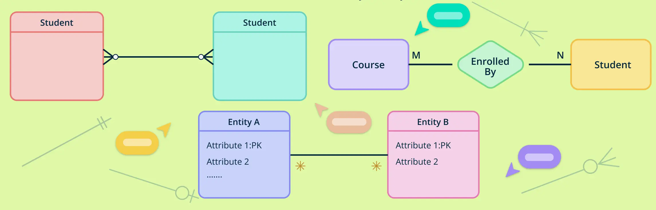
1. Crow’s Foot Notation (IE Notation)
Crow’s Foot notation is the most widely used method for drawing ERD foreign key relationships.
- Foreign keys are represented using a line that connects the foreign key attribute in the child entity to the primary key in the parent entity.
- A solid line is typically used, and the foreign key is labeled within the child entity.
- The foreign key field may be marked with “FK” or appear in non-underlined text, while primary keys are underlined.
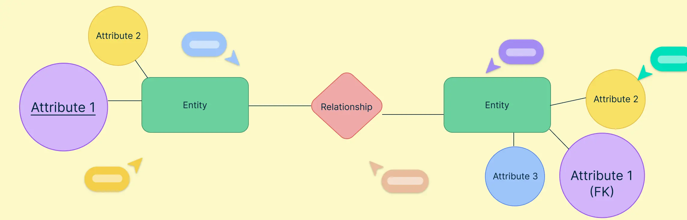
2. Chen Notation
Popular in academic settings, Chen notation uses a more symbolic approach.
- Relationships are shown as diamonds, with entities connected via straight lines.
- The foreign key in ERD is not explicitly labeled inside the entity but implied through the connection to the primary key of the related entity.
- Arrows or cardinality annotations near the diamond indicate the direction and nature of the relationship.
- The foreign key attribute may be added inside the child entity with a label like “FK”.
3. UML Notation (Unified Modeling Language)
UML is commonly used in object-oriented design but can also model foreign key relationships in databases.
- Classes represent entities, and lines (associations) connect them.
- A foreign key in UML diagrams is shown through an association line with multiplicity at both ends (e.g., 1..*).
- The foreign key may appear as an attribute in the class, with its type referencing the related class.
- Sometimes the foreign key field is annotated or accompanied by a note for clarity.


Examples of Foreign Key in ER Diagram
Understanding how foreign keys function in an ER diagram is essential for designing relational databases that are both accurate and efficient. A foreign key in ER diagram design connects two related entities, ensuring that data remains consistent across tables. By referencing a primary key in another table, foreign keys help maintain referential integrity and define meaningful relationships between data sets.
Below are several real-world ERD examples that illustrate how foreign keys are used to link entities such as customers to orders, students to course enrollments, and products to suppliers. These examples are perfect for anyone learning how to apply foreign key relationships in ER diagrams or for professionals looking to design clean, scalable database models. Let’s explore how these relationships come to life in practical database scenarios using Creately’s ERD templates.
1. Customer and Orders ER Diagram
This ERD example demonstrates a one-to-many relationship between Customers and Orders, one of the most common use cases of a foreign key in ER diagram design. In this template, CustomerID acts as the primary key in the Customers table and is used as a foreign key in the Orders table to associate each order with the customer who placed it. This structure helps maintain referential integrity by ensuring that orders cannot exist without a valid customer. It’s a foundational example for any retail, e-commerce, or CRM database model.


2. Student and Enrollment ER Diagram
In this education-related ER diagram, the foreign key relationship connects Students with Enrollment records. StudentID is the primary key in the Students table and serves as a foreign key in the Enrollment table. This setup allows multiple course enrollments per student, capturing a many-to-many relationship when combined with a Courses table. This ERD example is useful for understanding how to structure academic databases while keeping foreign key constraints clear and enforceable.


Read more: 10 ER Diagrams for a University Management System + Free Templates
3. Employee and Department ER Diagram
This ERD template shows how foreign keys are used in corporate or HR database systems. The Departments table uses DepartmentID as its primary key, while the Employees table uses the same DepartmentID as a foreign key to associate each employee with a department. This foreign key in the ER diagram example ensures organizational hierarchy and prevents inconsistent department references across records. It’s perfect for modeling company structures and departmental workflows.


Read more: 6 ER Diagrams for Employee Management System + Free Templates
4. Library System ERD
In this library database ER diagram, foreign keys help define relationships between Members, Books, and Borrow transactions. The Borrow table includes MemberID and BookID as foreign keys, referencing their respective primary keys in the Members and Books tables. This structure prevents invalid or orphaned borrow records and ensures every transaction is tied to a valid member and book. It’s a great example of using foreign key constraints in ER diagrams to build secure and accurate data relationships.


Read more: ER Diagram for Library Management System + Free Templates
Best Practices for Using Foreign Keys in ER Diagrams
Designing an effective ER diagram requires more than just connecting entities. It demands thoughtful use of foreign keys to ensure accuracy, consistency, and scalability in your database structure. Here are some best practices to follow when working with foreign keys in ER diagrams.
1. Use Descriptive and Consistent Naming Conventions
Foreign keys should clearly indicate their relationship to the parent entity. For example, using CustomerID as a foreign key in the Orders table immediately shows that the field refers to the Customers entity. Clear naming enhances readability and reduces confusion, especially in complex ER diagrams.
2. Normalize Your Data Model
Normalization is key to minimizing redundancy and improving data organization. Foreign keys play a vital role in supporting normalized structures by linking related tables instead of duplicating information. A well-normalized ER diagram with foreign keys helps ensure data consistency across all entities.
3. Enforce Referential Integrity with Constraints
Every foreign key value should reference a valid primary key in the related table. To maintain referential integrity, enforce constraints at the database level—this prevents orphan records and ensures that relationships between tables remain valid over time.
4. Define Relationships Before Building Tables
Before jumping into database implementation, take time to map out relationships between entities in your ER diagram. Identifying one-to-many, many-to-many, or one-to-one relationships early on helps you determine where foreign keys should be placed, ensuring your database is logically structured from the start.
Following these best practices not only helps you design better ER diagrams with foreign keys, but also leads to cleaner, more efficient databases that are easier to scale and maintain.
Helpful Resources
Discover ER diagram usage, history, symbols, notations and more.
Quickly create your ER diagrams online, collaborate with your team, maintain and track changes as the design evolves.
Design and visualize database schema with Creately's Entity Relationship Diagram templates.
Find out what Crow’s Foot Notation is, and explore how they bring clarity to the intricate world of entities, attributes, and relationships.
Final Thoughts: Building Stronger ER Diagrams with Foreign Keys
A foreign key in ER diagram design is far more than a simple connector—it’s a critical element that defines the integrity and structure of your entire database. By enforcing relationships between entities, foreign keys ensure your data is accurate, relational, and consistent. Whether you’re creating straightforward one-to-many mappings or modeling intricate many-to-many connections, understanding and using foreign keys effectively is essential for sound database architecture.
With Creately, you can visualize these key relationships effortlessly using intuitive drag-and-drop tools and professionally designed ERD templates. It’s the smarter way to design, collaborate, and optimize your data models. Start building your next database schema with Creately and see how easy and powerful relational modeling can be.
FAQs About Foreign Key in ER Diagrams
Can a foreign key in the ER diagram reference a unique key instead of a primary key?
How do you indicate a composite foreign key in an ER diagram?
Can a foreign key in the ER diagram be nullable?
What happens if a foreign key constraint is violated in practice?
Resources:
Frantiska, J. (2017). Entity-Relationship Diagrams. Visualization Tools for Learning Environment Development, pp.21–30. doi:https://doi.org/10.1007/978-3-319-67440-7_4.
Pigott, D.J. and Hobbs, V.J. (2011). Complex knowledge modelling with functional entity relationship diagrams. VINE, 41(2), pp.192–211. doi:https://doi.org/10.1108/03055721111134817.