Entity-Relationship Diagrams (ERDs) are the foundation of modern database design, offering a visual representation of how data is structured, connected, and maintained. As businesses and organizations rely increasingly on efficient data management, understanding ERD relationships is essential for designing scalable, well-organized databases.
This guide delves into the significance of ERDs, explores key ERD relationship types, and provides insights into best practices for ensuring data integrity. Whether you’re a beginner or an experienced database designer, mastering ERD relationships will empower you to create systems that are both logical and efficient.
Understanding ERD Relationship?
An ERD relationship refers to the connection between two entities (like people, objects, or concepts) in an entity relationship diagram. These connections are used in database design to visually represent how data is structured and related. Every ERD relationship needs to be clearly defined to maintain data integrity and professionals use many styles of notation to achieve this.
Why ERD Relationships are Important
There are multiple reasons why ERD relationships are crucial to modern database design.
Defines Data Structure ERD relationships establish how different entities interact, ensuring a well-organized database.
Maintains Data Integrity Properly defined ERD relationships help enforce constraints like primary and foreign keys, preventing data inconsistencies.
Reduces Data Redundancy By connecting related entities, databases avoid unnecessary duplication and enhance efficiency.
Enables Complex Queries Well-defined ERD relationships allow for powerful queries that can retrieve meaningful insights from interconnected data.
Ensures Logical Flow ERD relationships represent real-world connections, making it easier to map out business processes.
Supports Normalization They help break down large data sets into structured tables, improving storage and management.
Improves Scalability A well-structured database with clear relationships can easily adapt to future growth and changes.
ERD Symbols for Entities and Attributes
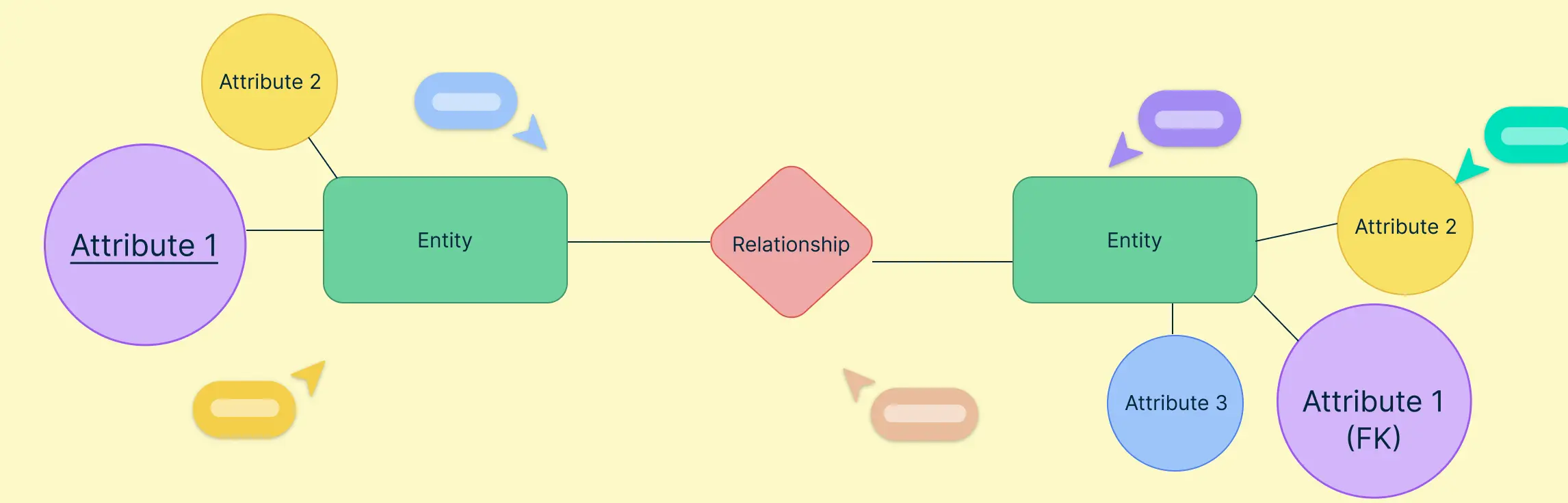
Entity relationship diagrams use entities, attributes and relationships to illustrate a database’s structure. Entities are the real-world objects or concepts that the database is tracking and storing data on. These are shown visually by a rectangle or table depending on the notation style used.
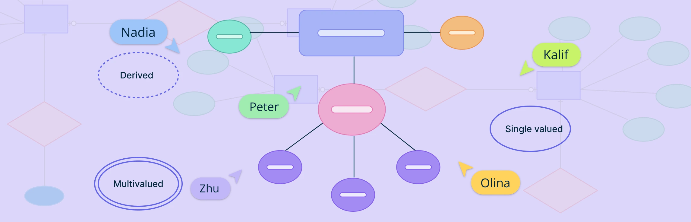
Attributes are the properties that describe these entities. These can be shown using ovals in conceptual models or inside the tables in more advanced logical and physical models.
In the example below, you will see two methods of how an entity called ‘Customer’ can be depicted. The image on the left is more conceptual with the attributes shown in ovals while the more advanced method on the right includes them inside the entity table. Both can be used depending on the application.

To find out more entity relationship symbols used in database design, read our guide on ER diagram symbols.
Understanding Cardinality and ERD Relationship Types
In an ER diagram, relationships stipulate how entities interact with each other. This is essential in structuring data efficiently and ensuring clear associations between entities. Cardinality refers to the number of instances of one entity that can or must be associated with instances of another entity. It indicates the optional or mandatory nature of ERD relationships.
It is cardinality that defines the minimum and maximum constraints of the following ERD relationship types.
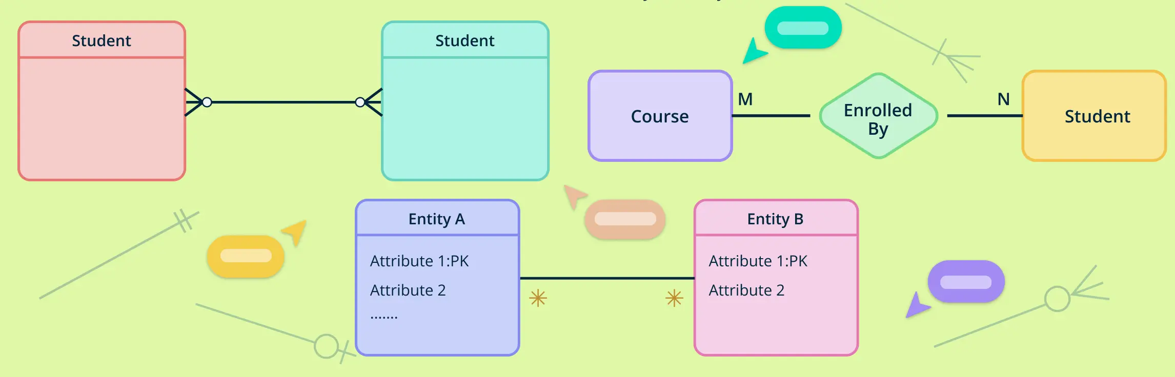
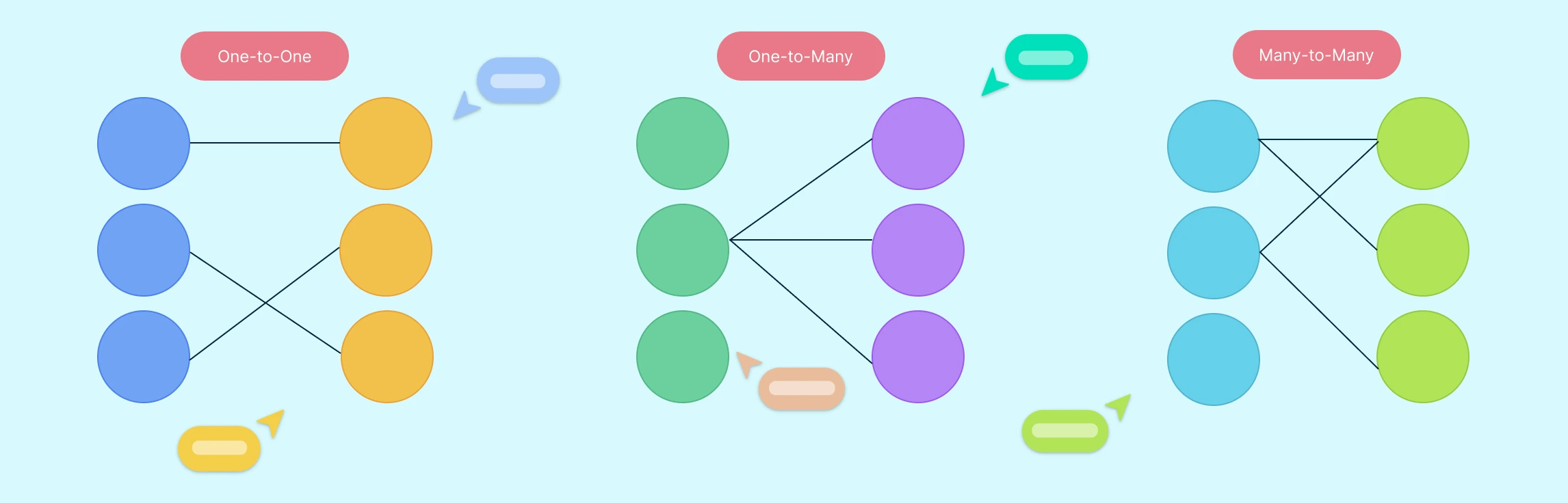
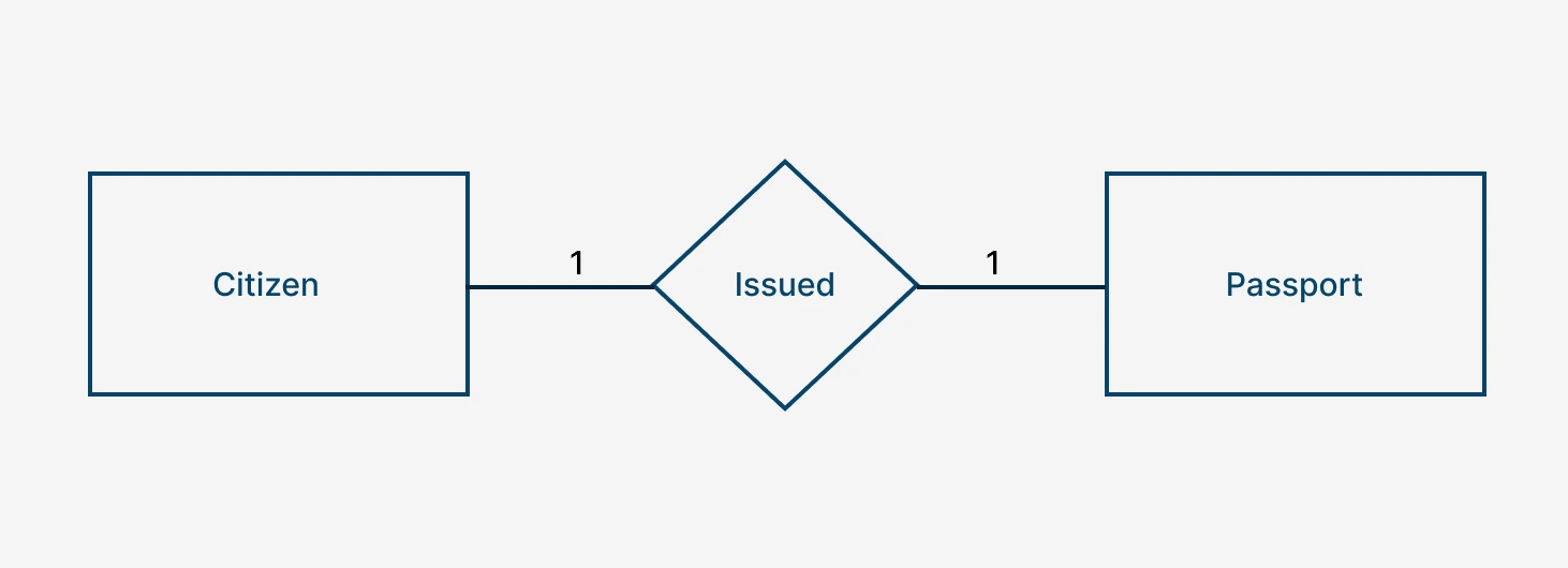
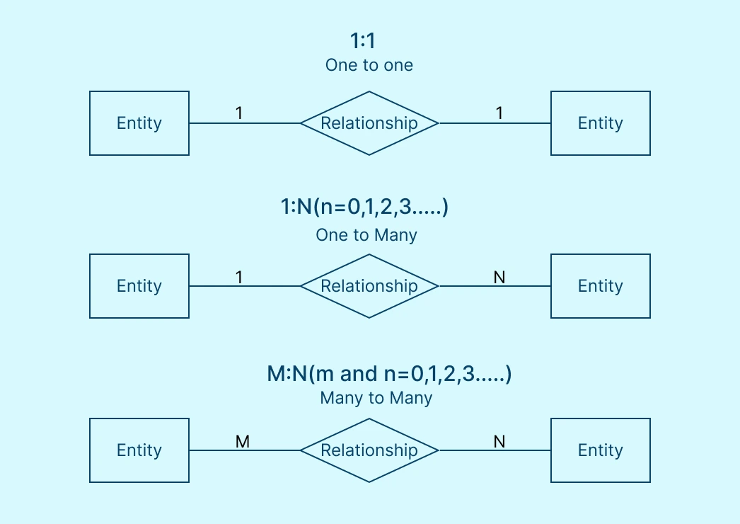
One-to-One (1:1) Relationships
Each entity in the relationship is linked to only one instance of the other entity. The issuance of a passport is a good example, since it is issued to only one person, and each person can have only one passport.
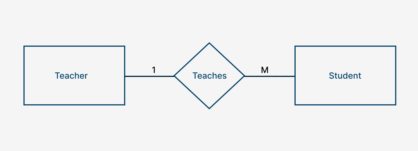
One-to-Many (1:M) Relationships
One entity can be linked to multiple instances of another entity, but the second entity is linked to only one instance of the first entity. For example, a teacher in a class can teach many students, but each student has only one assigned teacher. To learn more, check out our guide on One-to-Many relationships.
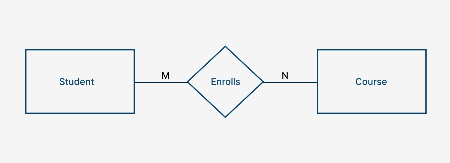
Many-to-Many (M:M) Relationships
Both entities can be associated with multiple instances of each other. This is like a student enrolling in many courses, and each course can have many students. To explore in detail about this type of ERD relationships, read our guide on Many-to-Many relationships.
Notations of ERD Relationships Explained
Cardinality can be visually represented in the ER diagram in different ways. Many styles of notation have been adopted by database designers in academic and professional settings depending on their specific requirements.
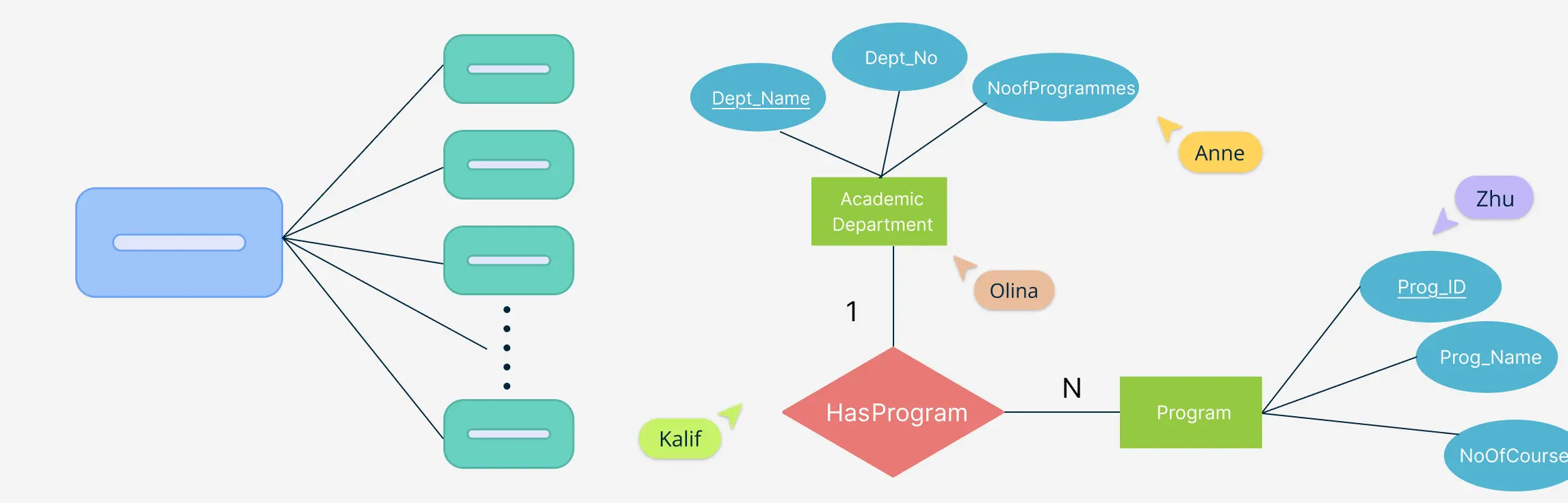
Chen Notation
Developed in 1976 by Peter Chen who pioneered many of the ER diagram concepts, this notation style is mainly used to educate students of database design. Its simplicity is its advantage, and is particularly effective in conveying the conceptual design of a complex database.
Chen Notation utilizes the standard symbols for visualizing entities, relationships and attributes. Cardinality is usually represented using numerical values like (0,1), (1,N), or (M,N) next to the connecting lines. These numbers indicate optional or mandatory relationships.
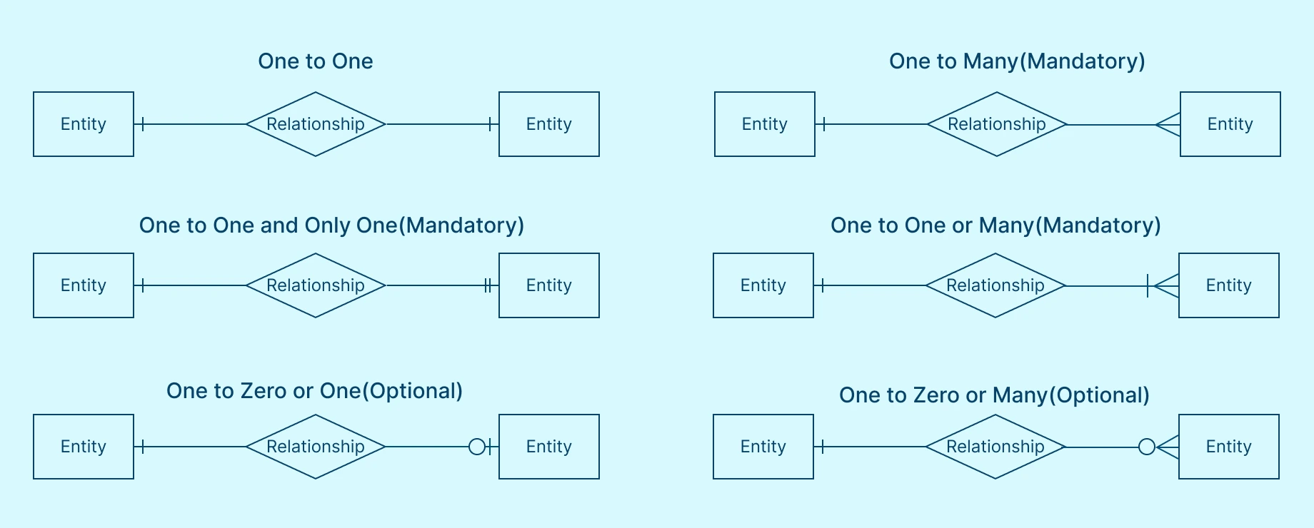
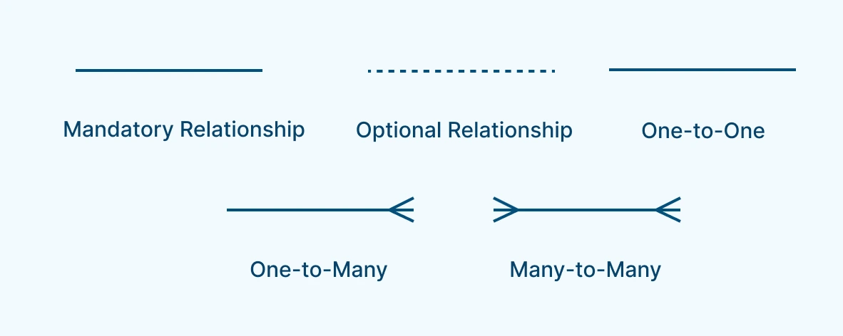
Crow’s Foot Notation
Instead of numbers, the Crow’s Foot notation uses a series of symbols that resemble a crow’s foot to represent the cardinality of the ERD relationships. This is sometimes referred to as the Information Engineering style.
The single vertical line represents one instance, with the circle indicating zero or optional instances. The titular three-pronged foot is for many instances. Additional complexity comes when optional and mandatory information.
Learn more about the history of the crow’s foot notation style and how to use it by reading our guide on crow’s foot notation.
Bachman Notation
The Bachman notation style is named after Charles Bachman, another data scientist who pioneered in this field during the 1960s and 70s. This notation is even simpler than the previous styles with only dots and arrows used to convey cardinality information.

Barker’s Notation
Richard Barker and his team developed a system of symbols in the 1980s which were later adopted by the Oracle Corporation for their standard database modeling. In Barker’s notation, the diamond symbols are no longer used to represent the relationships. All the cardinality information is shown by the connecting lines themselves with the various symbols at the ends.
Primary and Foreign Keys
Primary and foreign keys play a major role defining ERD relationships, ensuring data integrity and helping establish meaningful connections between tables. They become especially important when moving beyond the conceptual data models that provide a simple high-level view of the database to logistical models that utilize tables, columns and keys.
There are even more advanced systems based on physical models which add further complexity through data types and indexing. To learn more about the different types of data modeling, read this comprehensive ER diagrams tutorial.
Primary Key
A primary key is a unique identifier for each record in a table (entity). It ensures that no two rows have the same value for that attribute. They prevent duplicate entries and ensure accuracy. Without primary keys, tracking specific data would be chaotic
For example, in a Students table, the Student_ID can be the primary key because each student has a unique ID.
Foreign Key
A foreign key is an attribute in one table that refers to the primary key of another table. It establishes a relationship between two entities. Foreign keys enforce referential integrity, meaning linked records remain consistent and valid.
In a similar example, in an Enrollments table, the Student_ID can be a foreign key that links to the Students table.

Why Primary and Foreign Keys are Important in ERD Relationships
- Prevents data duplication and inconsistency.
- Strengthens the structure and relationships in a database.
- Ensures efficient data retrieval and organization.
- Supports normalization by structuring data properly
Common Issues in Defining ERD Relationships and How to Overcome Them
There can be many challenges when dealing with the many different ERD relationship types. Some of the most common issues are highlighted below with a few tips to overcome them.
1. Incorrect Relationship Definitions
Misidentifying relationships can lead to data redundancy and inconsistencies. For example, treating a one-to-many relationship as many-to-many can result in unnecessary duplication of data. The solution is to carefully analyze the nature of relationships between entities.
2. Complex Many-to-Many Relationships
Many-to-many relationships can create data duplication and referential integrity issues if not properly managed. You can introduce junction tables (or associative entities) to break down many-to-many relationships into two one-to-many relationships.
3. Confusing Attributes with Entities
Sometimes, designers mistakenly treat attributes as entities, leading to unnecessary complexity in the ERD. Clearly distinguish between attributes (which describe an entity) and entities (which represent objects in the system).
4. Redundant Relationships
Adding unnecessary relationships between entities can make the ERD overly complicated and difficult to maintain. It is best to avoid this by ensuring that each connection serves a clear purpose in the database structure.
5. Referential Integrity Issues
Poorly defined relationships can result in orphaned records or data inconsistencies, affecting database integrity. This can be solved by using foreign key constraints to enforce referential integrity and prevent orphaned records.
6. Scalability Problems
If relationships are not designed with future growth in mind, the database may struggle to accommodate new entities or changing relationships. Remember to always design ERD relationships with flexibility, ensuring that new entities can be added without disrupting existing relationships.
Best Practices for Designing ERD Relationships
Here are some best practices for designing ERD relationships to ensure clarity, efficiency, and scalability.
1. Keep It Simple
Avoid cluttering the diagram with too many entities or relationships. Focus on the core components to maintain readability.
2. Use a Standard Notation
Stick to established ERD notations like Crow’s Foot, or Chen for consistency. Ensure that symbols and relationship representations are clear and universally understood.
3. Define Clear Relationships
Accurately identify one-to-one (1:1), one-to-many (1:M), and many-to-many (M:M) relationships. Use junction tables for many-to-many relationships to avoid data redundancy.
4. Ensure Referential Integrity
Implement primary keys and foreign keys correctly to maintain data integrity. Prevent orphaned records by enforcing cascading updates and deletes.
5. Use Meaningful Naming Conventions
Choose consistent and descriptive names for entities, attributes, and relationships. Avoid abbreviations that may cause confusion.
6. Iterate and Refine
ERDs are not static. They should evolve as your understanding of the system deepens. Regularly review and refine the diagram to accommodate new requirements.
7. Optimize for Scalability
Design relationships with future growth in mind. Ensure that new entities can be added without disrupting existing relationships.
If you’re ready to start drawing, we teach you all the steps from creating entities, to defining ERD relationships in this how to create an ER diagram guide.
ERD Relationships Examples
If you’re still unsure how to use the different ERD relationship types, then do not fret. Creately has you covered with hundreds of ready-made templates to get you started with hundreds more examples you can learn from. It even comes with an automatic ERD relationship mapping feature, to suggest and help you connect the entities of your diagram. Here’s a few must-see examples!


Helpful Resources for ERD Relationships
Learn a brief history of ER diagrams, the basic concepts and the different data models in use.
A must-read guide on ER diagram symbols and the notation styles used by professionals.
Browse our vast collection of ER diagram templates.
Use our free tool to start making your own ER diagrams.
Conclusion
By learning to define clear ERD relationships between entities, enforcing integrity through primary and foreign keys, and selecting the right notation style, you should be able to begin designing efficient and scalable database systems. Whether developing small business applications or enterprise-level database solutions, a strong grasp of these ERD principles, combined with a feature-rich diagramming tool like Creately will ensure that your data remains organized, accessible, and meaningful.
Creately provides plenty of tools to streamline the design process. It is the perfect visual database modeling app, with an intuitive interface, pre-built templates, and collaboration features so your team can work together to refine your database. Check out Creately, the solution for database professionals aiming to build robust and future-ready systems.
FAQs about ERD Relationships
What is an ERD relationship?
Why are relationships important in ERDs?
What are the different ERD relationship types used?
- One-to-One (1:1) – Each entity is related to only one other entity.
- One-to-Many (1:M) – One entity is related to multiple entities.
- Many-to-Many (M:N) – Multiple entities are related to multiple entities.
What is the role of primary and foreign keys in ERD relationships?
What is referential integrity, and why is it important?
How do I choose the right ERD notation for my database design?
Resources:
Fahrner, C. and Vossen, G. (1995). A survey of database design transformations based on the Entity-Relationship model. Data & Knowledge Engineering, 15(3), pp.213–250. doi:https://doi.org/10.1016/0169-023x(95)00006-e.
Shoval, P. and Shiran, S. (1997). Entity-relationship and object-oriented data modeling — An experimental comparison of design quality. Data & Knowledge Engineering, 21(3), pp.297–315. doi:https://doi.org/10.1016/s0169-023x(97)88935-5.
Teorey, T.J., Yang, D. and Fry, J.P. (1986). A logical design methodology for relational databases using the extended entity-relationship model. ACM Computing Surveys, 18(2), pp.197–222. doi:https://doi.org/10.1145/7474.7475.